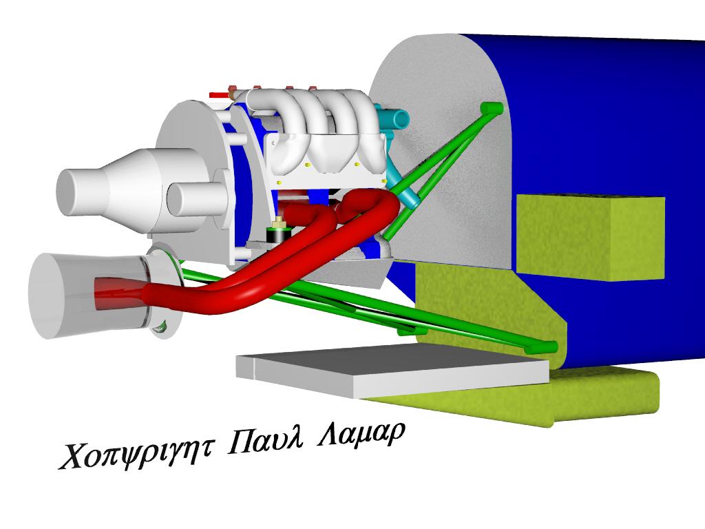
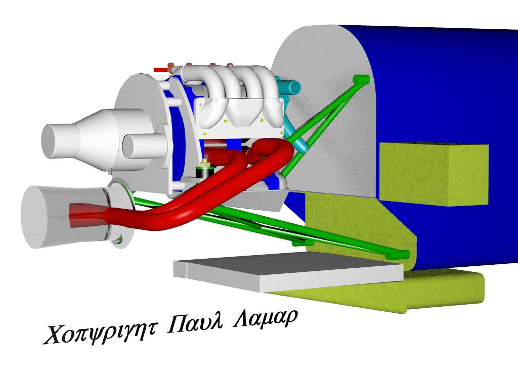
OK I got it!! This picture did it for me.

Do away with those silly box sections and sections of the
fuselage  that mount the lower motor mount tubes. Make steel  brackets that
picks up the landing gear bolts and fasten the tubes directly directly
to the landing
gear bolts. That is where the high G engine loads ultimately go anyway.
That will allow a wider and shorter rad, giving more room above the
rad for clearance and solve a whole lot of pusher cooling problems
not to mention doing away with some heavy redundant structure.
Mount the rad horizontal like before. this should work on every pusher
ever built. You can add a structural bulkhead from the bottom aft
edge of the spar forward to just above the landing gear bolts if you wish.

I'll do a 3D.

Paul Lamar
Here it is.

Looks like you can use a 16 by 19 by 2 inch rad and still get the
oil cooler along side. Nice and clean and simple.

Paul Lamar
Joseph Berki wrote:
Paul,
         This is a great idea!  I will replace the Al wedge blocks on the
aft LG bulkhead with a 4130 bracket that accommodates the lower tubes.  I
have been reading the SAE report on oblique radiators and was wondering
what are the dimensions for the wedge inlet and outlet?  This idea also
could be used on Cozy MkIVs and use the space in the hell hole.  Thanks for
the help.
Joe
You start with the required ratio of inlet area to core area of 25% to 30%.
Lets say the core is now 19 by 16 or 304 square inches including the oil
cooler. 30% of that is 91 square inches. Since the rad is 16 inches wide
divide 91 by 16 and you get the required depth of the wedge or 5.7 inches.
That would be about right for most 120 MPH airplanes. They tend to climb
slower.

My guess this might be a bit big for a high speed airplane so try 25%.
Also you might be able to get away with less as you are using a thrust
augmentor which will suck air through the rad at takeoff and climb speeds.
My guess is about four by sixteen ought to work in your case if the
augmentor works.  13 by 5 would also work.

My gut feeling is if the augmentor works as advertised this is
going to cool really well. Here is the 3D again in case anybody missed
it. It should work on any Rutan type canard pusher.

Cut off that useless fuselage structure under the spar and use the landing
gear bolts for the lower motor mount tubes directly. Saves weight and makes
the whole airplane stronger.

For the new guys one of the most severe design  requirements is for the motor
mount to survive is a hard landing. Up to 6 G's. This 6 G's is applied
on the main wheels when they contact the pavement. This puts a reactive compressive
load into the lower motor mount tubes up to 1500 pounds each. If this load
is fed directly into the landing gear the weight and stress applied to the
surrounding  structure is minimized. The same idea is used on every rear engine
race car built for the last 30 years. The rear suspension is hung
off the engine/transmission unit. Also the same idea is used on
the Questair Venture as the nose gear feeds landing loads directly into the
engine.

Paul Lamar

The AirCraft Rotary Engine NewsLetter.  Powered by Linux.
ACRE NL web site. http://home.earthlink.net/~rotaryeng/
Copyright 1998-2003 All world wide rights reserved.