Can you elaborate on the 'movement of the planetary ring gear' ? Was the
thrust of a helical cut gear being measured, or ????

This might have application in alternative engines with reduction drives.
Good Afternoon Charlie,

I can't tell you precisely, but that sounds about right.

The outer ring gear had helical cuts in the outer periphery such that it
would move slightly fore and aft as the torque was applied.  The ring gear pushed
on a series of pistons which then supplied a flow of oil to the instrument.
That was calibrated to be equivalent to the calculated Brake Mean Effective
Pressure which should have been developed in the cylinders to provide that amount
of torque.  By using a constant based on the displacement of the engine and
applying the RPM to the equation, the horsepower being developed could be
determined.

I know that regular oil pressure was supplied to the pistons to be used as a
transfer medium.  I have no idea how the pressure being developed by the
movement of the ring gear was isolated from the engine oil pressure.  I guess we
aviators didn't need to know that detail!

Happy Skies,

Old Bob
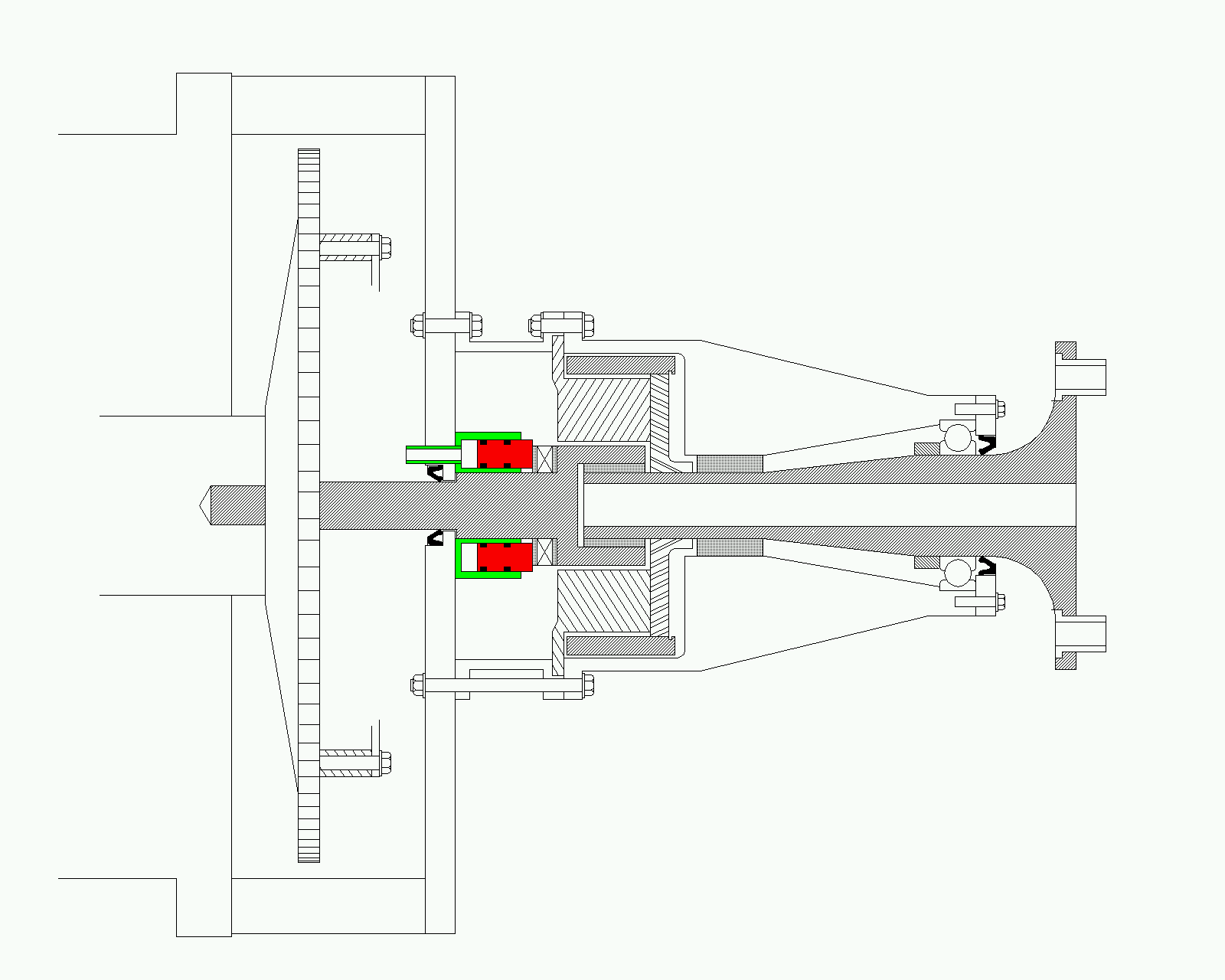
I thought of something like that over a year ago Charlie and uploaded a drawing.
I'll see if I can find the original messages on the CD. Here is the gif.

Paul Lamar
snips.........
Oh sure, load something else on my plate : )

I already added HP readout to the EM2 (based on fuel flow & BSFC).  I
know
this is still a theoretical rather than actual HP readout but for our
purposes it is very usable.

And I like the strain gauge idea.  Paul's annular piston would work
perfectly but would be impractical to implement.  But a strain gauge on
the
back of the adapter plate would be very easy and I just might experiment
with that.  Only possible glitch is that the hydraulic axial damping
system
on the input shaft (using oil pressure) causes an additional thrust on
the
sun gear that would have to be factored out of the reading. No big deal
if
the function were integrated into the EM2 which has access to oil
pressure
info.

But back in the real world, all my 'feature creep' energy on the
geardrive
is going into a chip detector system which will be an orderable option
when
ready. It is retrofitable to earlier drives too. Between that, the
2.85 :
1 RD-1C and the EM2, I'm tapped out just now. The strain gauge
experiment
will have to wait awhile.  Any volunteers?

Tracy
Why do you think this is impractical to implement? It is not nice
to make  hit and run statements like that :).

This is pretty easy to implement. No need for delicate strain gages and
strain gage amplifiers. (I did not just fall off the electronic
instrumentation
turnip truck. :)) I am not asking for any electronic changes. Just a
simple
addition to the gear box.

Paul Lamar
I meant impractical in the sense of what I have time for.  Mechanical
changes tend to snowball.  The adapter plate has to change to accomodate
annular piston assembly. The annular piston assembly would run into the nose
of the damper  so the damper would have to be changed.  The oil seal moves
back further on the input shaft where it is now splined so it would have to
be changed.

The strain gauge would simply be epoxy bonded to the back side of the
adapter plate.   The EM2 already has spare  inputs with  instrumentation op
amps.  Only thing to change would be the gain setting resistors for the
proper sensitivity.

If I only have one life to live, let me spend it flying instead of standing
in a machine shop : )

Tracy
Here is a picture of Tracy's input shaft, thrust bearing and oil seal.
Note there is room between the thrust bearing and the planet carrier
to put the dyno. It would mean grinding some of the useless sun gear
material away and moving the thrust bearing closer to the planet carrier
with the annular cylinder behind it. The space available for the annular
measuring cylinder is then about 1-1/8 inches long which is
plenty.

Tracy's hydraulic damping feature
adds roughly 125 pounds to the thrust bearing loading at 90 psi engine
oil pressure so that must be subtracted from the measured torque load.
The input shaft area the engine oil pressure works on is about 1.389 square inches.
Due to the fact of a bleed hole in the sun gear and bearing clearance
leakage it may not be the full 90 psi on the input shaft so we will have to
measure that thrust load while the engine is running with no prop and the
psru generating minimal prop torque. It would not be accurate to merely
measure or note the engine oil pressure.

The data this device provides allows one to measure the actual HP
the engine is generating at any RPM at all times while flying which is
very handy when trying to figure out what fixed pitch prop to use
and the fuel burn. Basically it is a super cheap dyno.

If anybody is interested I could do a batch of these things as a retrofit.
You will need to send me your input shaft and I will have them all ground
at the same time.

Cost on the whole thing will be in the $300 ball park.
Any takers?

Paul Lamar
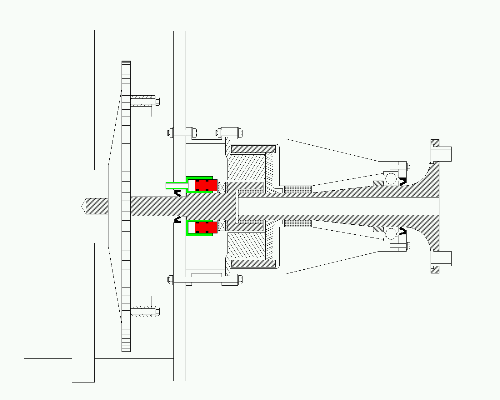
Here is a new drawing on the device. A bit more accurate than the last one.
Only one mod to Tracy's redrive and that is to the sun gear. Easily retrofitted
to Tracy's redrive.

Paul Lamar

The AirCraft Rotary Engine NewsLetter.  Powered by Linux.
ACRE NL web site. http://home.earthlink.net/~rotaryeng/
Copyright 1998-2003 All world wide rights reserved.