George Lendich wrote:

Paul,
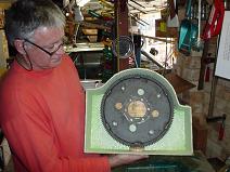
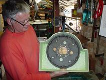
Yep this is the Auto flex-plate, 320mm.
Now just in case someone does have a flywheel that's little bigger - it will take that as well.
There are a number of flexplates, wouldn't have a clue what this is off, maybe an early 13B. Anyhow the 320mm is the magic
number by what everyone has said in response.

I haven't had a chance to check thoroughly yet but it appears that I may not need stand-offs at the top.

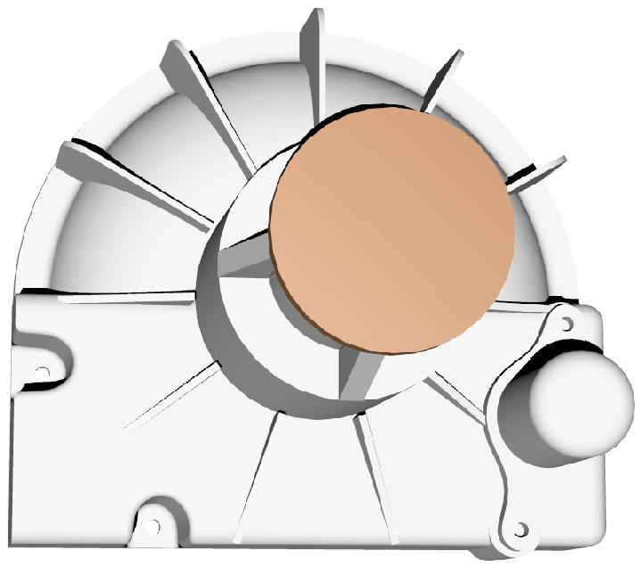
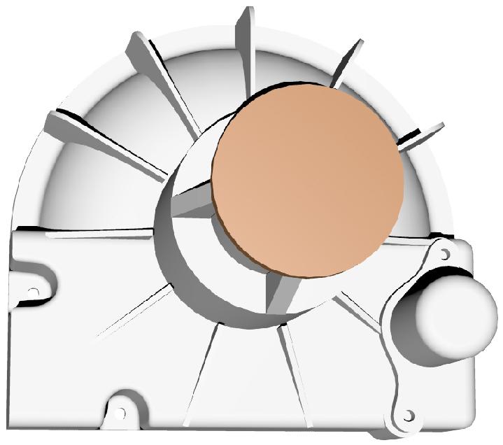
Is this picture good enough for you to assess internal stiffeners.

On the thick centre area for the PSRU mounting, I was wondering if the face is the better place to put the extra thickness, it
helps to blend in the ribs and is more easily milled-off (as a raised area).
This does in effect make the overall length alittle longer -10 mm longer in fact.
It does eliminate a possible stress raiser in the milled area as well.
What's your thoughts?
George (down under)
PS. In looking at your drawing for the lower mounting holes, I'm wondering if the cut-out at the side will reduce strength in
the engine mounting section. Also if I use solid stand-offs I could make them part of an internal rib - extra strength
The starter needs to be spaced out the same as Tracy's redrive so a flat front surface
is called for. Put the internal ribs everywhere the flex plate and starter are not
on about 30 degree increments. Only in the lower half. the upper half will
have the external ribs.

The cut out on the side will not reduce strength as it will be bridged by the
bolted on rubber bushing holder motor mount bracket. This will save weight
in the bell housing bolts.

Paul Lamar

The AirCraft Rotary Engine NewsLetter.  Powered by Linux.
ACRE NL web site. http://home.earthlink.net/~rotaryeng/
Copyright 1998-2003 All world wide rights reserved.