George Lendich wrote:
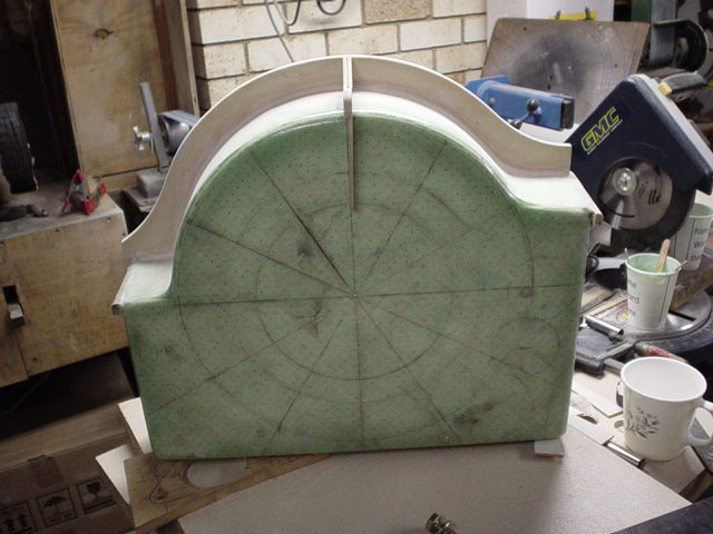
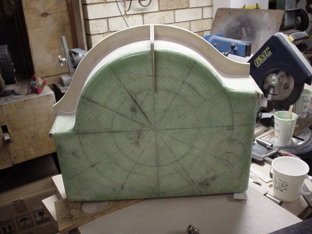
Those stiffeners finishing at the face should they have a curved edge as
compared to an abrupt square edge - I'd prefer the
curved finish for aesthetics but don't know about the best approach for
stress transfer.
George (down under)
Looking good George. Carry them around the bottom flat face where
possible.
The square edge will mate nicely with Tracy's psru. You will need maybe a
5 mm radius just so it pulls from the sand cleanly. When assembled it will
look great.
You are a pretty good pattern maker.

Paul Lamar
Thanks for the encouragement, I need it, I'm getting to the real tedious/
critical bits.
I used your Perspex idea and found my original bolt pattern was out a
little - measure twice cut once !!
at this point.

So just to clarify --- the stiffener as shown is too rounded, you would like
it sharper to match Tracy's PSRU - about 5mm at the corners - OK !!

You will notice the starter pattern lower bottom left of pictures.

George (down under)
No pic attached George.

Paul Lamar,
Sorry Paul,
Trying to avoid sending the same photos again and again.

Your drawings display the stiffeners as round at the top and squarish at the face centre, as this attached picture shows.
However I'm not quite sure exactly this is how you want them. I just feel if it's too square at the top corner, they will look
too large i.e. 30mm to 20mm to 10mm.

It may be the small radius you speak about is for the ones which terminate at the sides (engine mount areas).

Just a tad confused on this issue, but want it to look right too.
George (down under)
We got that one. Here it is again. The stiffeners look fine and of the right
size. One can always cut them down if one wants to live dangerously :)

BTW you can use a hole saw to cut large holes between the stiffeners if
you need to inspect the guts.

Paul Lamar
david mccandless wrote:
Hi Paul and George, I notice you have the engine mount bolts in shear in
this rendering, not recommended with steel bolts into aluminium. It
leads to radial cracking around the bolt holes. Better to cast in a
shoulder, or mill a shoulder if there is enough metal, so that the bell
housing rests on the engine mount interface and have the bolts stressed
only in tension. I did note that a 3-4mm steel plate could be mounted
INSIDE the vertical faces to spread the vertical loads with the mounting
bolts passing thru the alum. side faces in a sandwich grip. Nice job
there George.

Ref Plugs Up, I thought Ed Anderson's installation disproved all that
hokem about oil paths and cooling. A local guy here raced a 12A "plugs
up" in a boat some years back and had none of these problems.  (I admit
cooling a boat engine in water should be simpler). With turbo
installations, it can make turbo oil return to the sump a bit awkward.
Any comments Ed ?

Ref End Housings. Paul, I know you are busy with the Dyno, and water
pumps etc but any news on the ?  Dave McC
We got the shoulder Dave. Take a close look at this picture.

On the subject of plugs up. Why ask for trouble when there is absolutely
no advantage in running it other than the way God and Mazda intended?
Are you trying to start trouble Dave? :) If you just want to be different
trying running it up side down :)

I would not hold my breath on the alum/steel end/center  housings. The
machine shop that was doing the work dropped the ball on stuff he was doing for me.

George is a good pattern maker. Perhaps we can talk him into doing
the pattern.

Paul Lamar

The AirCraft Rotary Engine NewsLetter.  Powered by Linux.
ACRE NL web site. http://home.earthlink.net/~rotaryeng/
Copyright 1998-2003 All world wide rights reserved.