snips.....
Paul,

I see where Bob Darrah is coming from, and you are both right. However,
with your current setup, you can only get meaningful data when you
pressurize the system such that the inlet pressure guage never goes
negative. As long as the total system is pressurized, then you can read the
inlet and outlet pressure readings and get the delta-P. Alternatively, get a
negative reading pressure guage for the inlet.
If I recall your first run, (unpressurized), the pressure was very low,
for the reason that Bob stated, since the air column could compress, you
couldn't raise the pressure on thepump outlet. What was happening was the
inlet pressure was going to about -12 psi.  After you pressurized the
system, then you could read both gauges, and got a delta-P of 12 psi.
Several items to consider in any of these tests:
1. The pressure generated by the pump is a function of the RPM ( I
believe it is a function of the square of the RPM)
2. When dead-headed (zero flow) you get the maximum available pressure.
3. When you allow flow, the pump (at a given RPM) generates the same
pressure as at zero flow, MINUS internal losses -- the internal pressure
drop in the pump.  So with your tests, the flow goes to a high value because
there is little restriction, however the delta-P across the pump is
essentially the same (minus the internal losses).  That means that the
balance of the system requires ~75 GPM to get the offsetting pressure drop.
4. When you put other components in the system (engine block and
radiator), the delta-P across the pump will *remain the same* at a given
rpm, but the flow will drop off dramatically due to the pressure
restrictions of the flow through the balance of the system.
If you could measure several points of dead-head pressure as a function
of RPM, say 1000, 2000, 3000, 4000, 5000 that would be really useful
information.
Bill Schertz
KIS Cruiser # 4045
I filled that "stand pipe" to the top. There may have been a quarter inch
of air in there.
In fact the last time the pressure went up one or two psi as I screwed the
cap down.
There is no column of air. The gage will be here any minute. I won't get
to
test again until Wednesday as tomorrow is Robins birthday.

Lower RPM's are not of much interest to us but I will make another run
at a lower RPM.

Paul Lamar
The data certainly suggests that there is something very amiss with your
test set up.
Why? How much data have you seen on CLOSED LOOP systems?

What goes out the pump goes in the pump. What goes around comes
around.
You do not seem to be developing anything like the pressure that one would
expect for the rpm. Bill's data seems much more as one would expect.
Bill's data was taken by an OPEN LOOP SYSTEM!!!!!!!!!!!!!!!!!!!!!!

Any pressure on the outlet side is not reflected on the inlet side.
If you want to characterize the pump performance, the attached figure
shows about a minimum complexity setup. Also if you want to measure
the flow resistance of the block or radiator just put it in the circuit in
place
of the valve. The reservoir will minimize heating with the increased thermal
mass, and the system will be self priming .

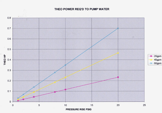
Also the amount and pressure of water flow that we are dealing with is
not all that power hungry. the attached curve shows the theoretical
pumping power required at 60 gpm and 20 psid is less tha 3/4 hp
50 percent efficiency should be possible with a good pump
Vance
The figure you spoke of was missing. In its place was a prop thrust curve.

Here is the second jpg you sent which seems relevant.

Much of the heat is due to the inefficiency of the belt drive
I am sure. Side loads on bearings etc. etc.

If you are not doing anything on Wednesday come on over to the
hangar and witness the test.

Paul Lamar

The AirCraft Rotary Engine NewsLetter.  Powered by Linux.
ACRE NL web site. http://home.earthlink.net/~rotaryeng/
Copyright 1998-2003 All world wide rights reserved.