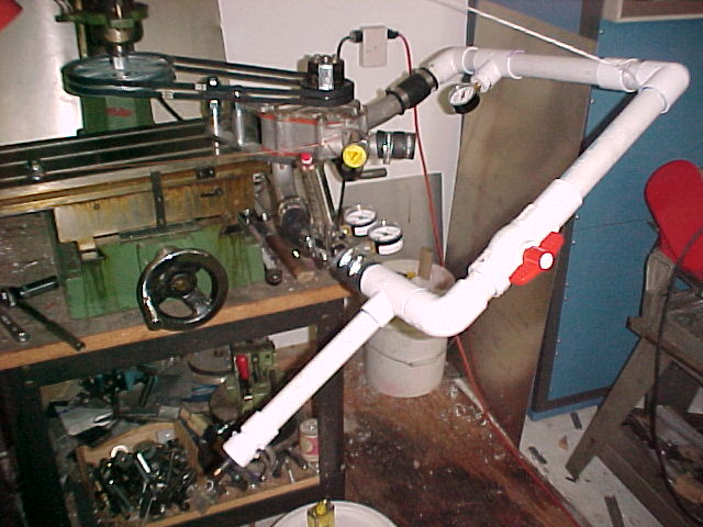
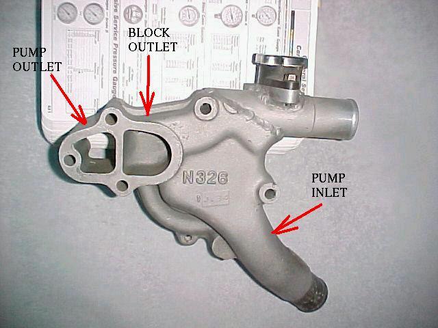
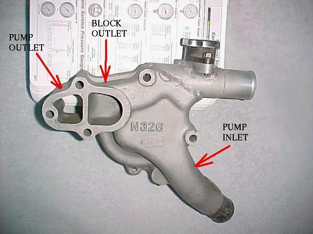
Here is the data at 4300 RPM for the stock Mazda water pump. No pre pressure.
Pressures in psi. Pump outlet, flow meter, inlet respectively.
Flow in gallons per minute.

Flow      Press 1   Press 2 Press 3

Closed     10        10       2
15         5         5        2
20         5         5        2
25         5         5        2
30         5         4.5      2.5
35         5         4.5      2.5
40         4.5       4        2.5
45         4.5       3.5      3
50         4         3        3.5

stopped    3         3        4

The water heated up some so the final pressure was higher
than the initial pressure.

Obviously if you are looking to up the pressure in the block by adding
a restrictor you are barking up the wrong tree. All you would be doing
is cutting the flow. This may or may not be good depending on your goals.
Our main goal, assuming the metal is adequately cooled, is to prevent
boiling.

Less flow may mean lower water temp but higher cylinder head temp
for lack of a better term. Nobody, and that includes me, have measured the
temperature in the rotor housing within 2 mm of the combustion chamber.

So far that has not proved to be a problem in the Mazda as I can not
detect any deterioration of the rotor housings in this area due to overheating.
Yes the rotor housing shrinks if over heated but I am not sure if increased
water flow is the answer. Usually this happens when the engine runs out of
cooling water or the water level drops below the pump intake and the pump sucks
air.

If you are running a restrictor and you are happy with the cooling you can
achieve the same thing by slowing the RPM of the pump and probably suck less HP
to drive the pump in the bargain.

A piston engine with an aluminum cylinder head is another matter. They do indeed
show signs of failure if inadequately cooled due to inadequate flow of cooling
water. And that goes for the exhaust valve in spades.

All these tests confirm the proper place for the expansion tank and pressure cap
is between the rad and the pump inlet to delay boiling. Not between the block
and the rad as is common on passenger cars. The pressure in the system on average
will be much higher. I think placing it between block and rad  is traditionally
done on passenger cars as it is a convenient place to put the expansion tank and
pressure cap. In our case with the rad frequently mounted under the engine it
does not matter where the tank is plumbed in.

Now having said all that a bit about the ability of a rad to withstand higher
pressures. A wide thin tube wants to deflect towards a cylindrical shape
when pressurized. It is therefore better to have two rows of narrower
tubes with the same over all rad depth.

Paul Lamar
Here is the test data when the system was pre pressurized to 20 psi.

Closed   24    23.5   14
15       22    21     14
20       22    21     14
25       21.5  21     14
30       21    20.5   15
35       21    20     16
40       21    20     16
45       20.5  19.5   16
50       20.5  19     16
55       20    19     16
60       21    19     17
65       21    19     17
70       21    18.5   17
75       21    18     17.5

stopped  18    18     19 slight pressure leak.

Notice that there is very little pressure drop across the pump
at the higher flow rates. The stock pump has about a 1/8th or 3/16th bleed
hole between input and output accounting for the slight pressure difference
over the new casting. also I suspect it has a bit more clearance. Will check
that using the clay test later in the week.

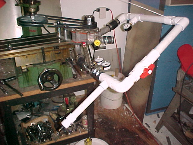
Here is a picture of the test set up again.

BTW be careful when using RTV to seal the pump. A small particle broke loose
and plugged the flow meter. I had to stop and clean it out and re run
the test. It is possible for a chunk of RTV to also plug the bleed hole
in the stock pump.

If this data does not seem right to you by all means drill a few 11/16th
holes and tap them 1/4 NPT in your stock pump and install some pressure
gages to verify or disprove my data. Do this before and after you install
the restrictor if you think a restrictor is the way to go.

I have been getting a bunch of email from one unnamed person who claims
this is all wrong but he is unwilling to build his own test set up
and instrument it to provide data to support his claims.
If you are tempted to send me such email please back it up
with real data first. I spent considerable time and money to do this
and I think it is done right.

I will not be able to finish machining the pumps until well after
OSH. I need to make a drill jig for the cartridge mounting holes
as that is the only way to insure the impeller is centered in the
housing.

Paul Lamar

The AirCraft Rotary Engine NewsLetter.  Powered by Linux.
ACRE NL web site. http://home.earthlink.net/~rotaryeng/
Copyright 1998-2003 All world wide rights reserved.