Al Gietzen wrote:
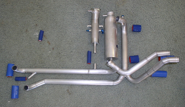
Here are the pieces for my coolant plumbing for my Velocity 20B, just in
case it stimulates any thoughts or ideas.  I'm going for the 'most
complicated' prize.

On the left is the connection to the in-cowl radiator, and the
connection for the heater return.  On the right is the connection to the
radiator in the wing.  Center is the pump outlet (top) and pump inlet
(bottom).  The smaller 'bottle' (2" tube) is the filler neck for the
system with a 25 psi cap, and connects to the pump inlet side.  It has
fittings for the air bleed lines from both radiators.

The pressure relief from the filler neck connects to the bottom of the
larger 'overflow' bottle made from a fire extinguisher.  That bottle
will have a 15 psi cap; any over flow goes overboard. The concept is
that the pressurized overflow bottle will maintain an air volume
compensating for expansion; there will always be some pressure on the
inlet side of the pump (even when reducing power) and the system will
immediately return to inlet side pressure of 25psi when power is
applied.

All this stuff mounts against the firewall in about the same way it is
laid out here.  More later.

Al
The AirCraft Rotary Engine NewsLetter.  Powered by Linux.
ACRE NL web site. http://home.earthlink.net/~rotaryeng/
Copyright 1998-2003 All world wide rights reserved.