Paul Lamar Wrote:
The two rear conical mounts in your set up have near zero load as the
CG
of the
engine prop psru combination is located about where the front conical
mounts
are located. That heavy rear cross beam is doing nothing and is along
for the ride. You could also save more weight by mounting the front
rubber
mounts on the psru adapter plate and bypass most of the loads on
Tracy's
plate
spacers and long 10 mm bell housing bolts. This would get the front
rubber
bushings 3 inches further away from the 1400-1800 degree F turbo
housing.
This would then eliminate the large heavy plate you have sandwiched
between Tracy's
spacers and the front end housing of the engine. I also see no
diagonals
laterally bracing the front rubber bushing holders.
It is a little bit of an exaggeration to say that the rear mount does
zero.  With the psru mounted (no prop or coolers - but also no
alternator, turbo, manifolds, oil, or coolant) it took about 60 pounds
to lift the rear (front cover) end of the engine while resting on the
front mount.

I cant imagine how my design would put more stress on the 10mm bolts
than moving the mounts forward to the adapter plate.  The spacers don't
even know my plate is there.  The designer of the PSRU (Tracy) does not
recommend using the adapter plate as an engine mount - and it makes
sense to me that it would place too much stress on the bolts, bolt
connection to the engine block, spacers, and possibly cause twisting and
flexing of the very close tolerance adapter plate.  I showed Tracy my
design and he approved it with the caveat that it looked too heavy with
that extra alum plate.  You are very correct about that extra weight,
but I decided to err on the side of safety over weight and decided that
I did not have the ability to make a more elegant design. (This was
relatively easy to do, though in retrospect I would probably go with an
oil pan plate like Tracy - Fred, where were you?)

That heavy rear cross beam is actually not connected to the engine
mounts, but is part of the landing gear mount and prevents the gear from
collapsing on 'slam'-down.  It was part of the original RV-6 mount (I
know it is hard to tell from the picture).

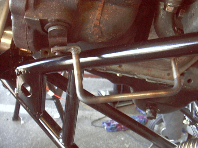
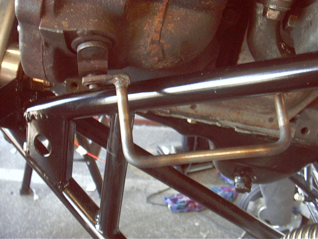
I'm not sure what you mean about diagonals for the front holders.  Look
at these pictures.  There are 2 lower and 1 upper supports going to each
of the front bushing holders with a curved support (probably not needed)
connecting the two.
Not that I expect you to do any of this as there is nothing really
unsafe
about your
design perhaps with the possible exception of the non-existent lateral
bracing but it is a
good example of why this is not a good approach. On the other hand you
have known
about my approach to motor mounts as you have been on here a long time
I
therefore
have no sympathy for you :) As I recall you and I had a bit of
communication on this
subject a year or two ago when I criticized a similar mount on someone
else's
airplane. Little did I know at the time it was personal :)
I actually listened to you then,  I had been debating the need to add
the 2nd lower support tubes and decided in their favor based on that
discussion.  See?  I care what you think  :-)

Dave Leonard
Those vertical tubes between the upper and lower tubes are a no no.
I would cut them out. Also the channel section gussets are way
too strong. Both things will lead to bending induced stress
concentrations in the upper and lower tubes right where those parts
are welded in. They add noting to the strength of the motor mount.
On the contrary actually.

Paul Lamar


The AirCraft Rotary Engine NewsLetter.  Powered by Linux.
ACRE NL web site. http://home.earthlink.net/~rotaryeng/
Copyright 1998-2003 All world wide rights reserved.