Ed Anderson wrote:
Hi Paul,

    You asked about the new inlet duct modification.  I mispoke - its
more
like 15-20deg/inch rather than 7. I attached my excel spreadsheet where
I
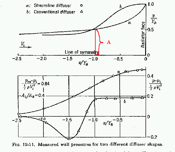
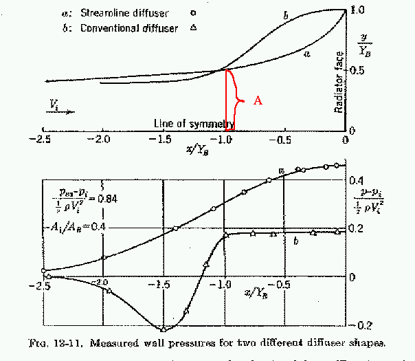
attempted to use the "a" (alpha curve) for a streamline diffuser (I
believe
you provided the figure I pasted into spreadsheet)  adjusted to fit the
fiberglass ducts I had.    I suspect that while the more gradual curves
will
probably help the flow that I might have been overly zealous in reducing
the
inlet opening size as much as I did. But I can open it up as required.
Not
a perfect fit to the theoretical by any means, but probably better than
the
bowl shaped inlet I had previous - first flight will tell.

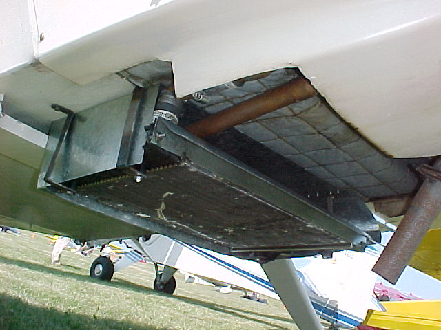
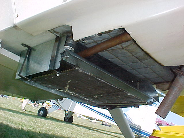
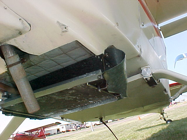
Here are a couple of photos that may help, although the curve from inlet
to
radiator doesn't show up all that well due to last of contrast/reference
point.  Guess I should have held a straight ruler or something agains
the
fuct to show it.

 I first filled the duct with the liquid expanding foam, then shaped and
added some lightweight filler to smooth the surface. I used the paper
templates (Mvc33)to try to stay as close to the spreadsheet curves as I
could.

Ed
I used to think that was the way to go but now, if you notice, the
length of the K&M diffuser needs to be 2.5 times the height of the rad
to prevent separation.

Lets say your rad is 10 inches high. Obviously you don't have 25 inches
in length to work with. It is possible however if you opened up the inlet
area to a larger percentage of the core area (from 25% say to 50%)
you could use a shorter K&M diffuser with out separation. You have closed
it down which seems a bit odd and opposite to what might work:)
I guess we shall see.

In any event I think you are better off with a cowl flap as closing the
cowl flap will build back pressure in the duct and cause external
diffusion
thereby automatically streamlining the inlet externally.

On the other hand the Kays & London simple wedge shaped diffuser requires
no more length than the rad lying on its side. I now think this
is the best approach as it uses a minimum of under cowl volume or space.

Paul Lamar
Ed,
I am very interested in how your tests go with the revised ducts, since you
had pretty good cooling with the original ducts.

Bill Schertz
If you plan on using Kucheman & Weber principles for the duct shape
.... you are limited in duct length by using dual evap cores I would
enlarge the opening to point A on the curve. You will pay a very small
drag penalty if you use a cowl flap in conjunction.

All this assumes of course the core is perpendicular to the axis of the
duct which in general is not the case with the use of dual evap cores.
The evap cores are usually mounted at some angle to the longitudinal
axis of the plane and not in perfect alignment with the scoop opening.

So in real life no telling what the flow distribution through the
core will be. If I were doing it I would build a test set up
for the Dodge Van and use four or more pito tubes behind the
core and check the uniformity of flow through the core with the
new duct and scoop.

If there are any engine parts within five inches behind
the core that too would also affective flow distribution.
In other words this approach is highly sensitive to small
differences in configuration.

I would not be a bit surprised if Ed's new duct and smaller scoop
worked worse than his old duct and scoop.

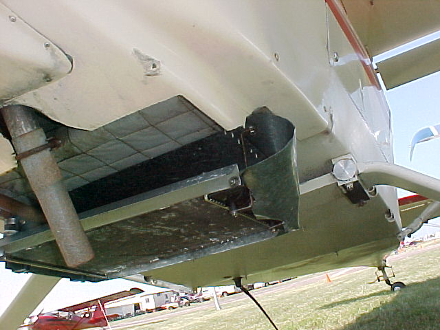
BTW these last pictures show my favorite way of mounting the rad :)
In theory it is near perfect. The drag increase will be minimal.
IMHO the guy that thought this oblique rad mounting up was a genius.
Can't claim the cosmetics are all that great but that can fixed.
It can also be improved slightly by dropping it down a little
more to bypass the boundary layer.

Paul Lamar

The AirCraft Rotary Engine NewsLetter.  Powered by Linux.
ACRE NL web site. http://home.earthlink.net/~rotaryeng/
Copyright 1998-2003 All world wide rights reserved.