Do you have any pictures of the motor mount area Scott?
The official Glass Goose web site crashes my browser.
No way to run a business. They should fix the web site.

Do you know how to capture pictures off the web?
In NS you put the mouse pointer on the picture and press the
right mouse button and select "Save Image As.."
Find and send some pictures to me and I will do a 3D on the
motor mount.

Paul Lamar
The Glass Goose plans have pictures of the 0-320 installation as
well as engine mount design drawings, but no overall technical
drawings.  I've been unable to locate any detailed drawings to date.

I have attached several photos and one drawing that might be adequate
to determine a solution to this problem.  These include:

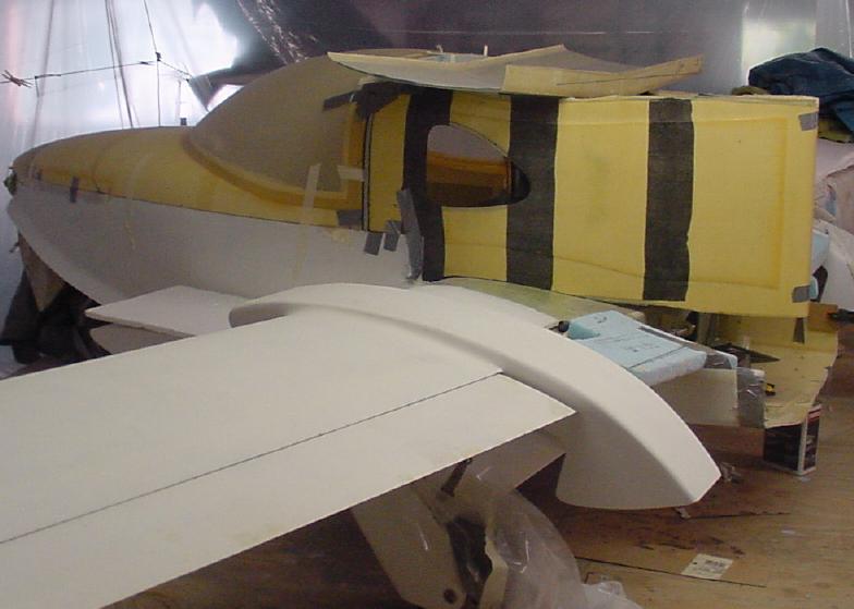
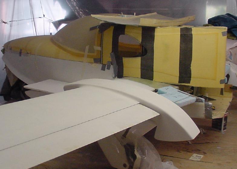
*GG Pylon Fitting 3.jpg, which shows the installed position of the
inter-wing pylon, including its lack of aft support.  This
aft area gets glassed into the tail assembly, but will have little
vertical load capability.

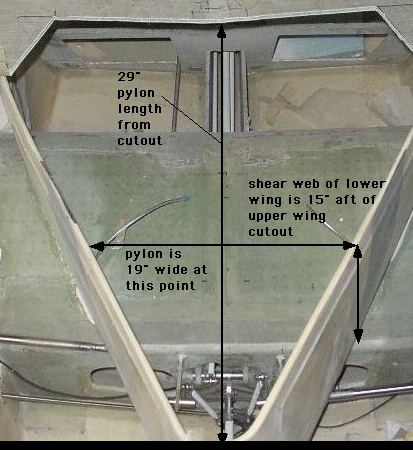
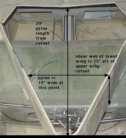
* GG Pylon 1 and GG Pylon 3 are pictures of my current pylon,
including a dummy upper wing skin showing the engine cutout.
Various dimensions are included.

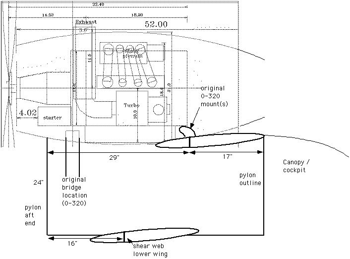
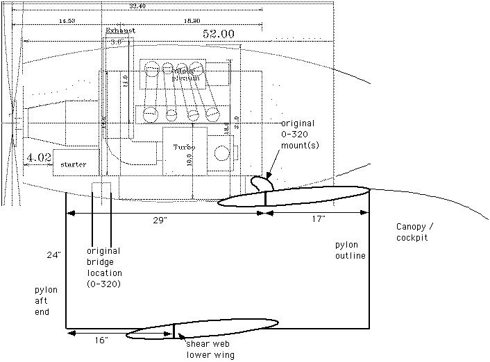
* GG 13B side is a crude drawing showing the side-view dimensions
of the pylon, the original engine mount locations, and an
overlay of a 13B engine and the cowling.  Note that the engine
sits well above the pylon, so the narrow aft width only applies
to the engine mounts below the engine.   Also note that the motor
plate is right over the original, aft bridge mount, which is
in the narrow and relatively weak area of the pylon.

On a second e-mail, I will attach 5 photos of another builder's
(quite impressive)13B installation.  This builder used 4 mounts:
two at the normal auto-engine location, with one front and one
aft mount.  The center mounts require a new bridge inside the
pylon, but it is right over the (very strong) lower wing shear
web.  The aft mount is the same as for the 0-320.  If a single
bridge support could be used, even if it angled down from the
necessary engine location forward to the lower wing shear web, it
would seem less complex and much lighter than using two bridges.

If I am correct, the compromise appears to revolve around:
1.  Getting the rear mount(s) as far aft as possible
2.  Having adequate structural support for these mounts
3.  Having enough width in the aft location for two mounts.

Would two, narrowly-spaced aft mounts at the end of the
engine block or motor plate based on a single bridge, combined with two,
widely-spaced forward mounts make sense?

Hopefully this is enough information to formulate a recommendation.

Scott Gettings
OK Scott looks possible. I'll work on it. You don't really need width
for the aft mounts. The front mounts can accept the prop reaction torque.
If you don't have a 12A front cover Rick Girard has one for sale.
Snap it up :) Perfect for your use.

Paul Lamar

The AirCraft Rotary Engine NewsLetter.  Powered by Linux.
ACRE NL web site. http://home.earthlink.net/~rotaryeng/
Copyright 1998-2003 All world wide rights reserved.