George Lendich wrote:

Paul and Butch
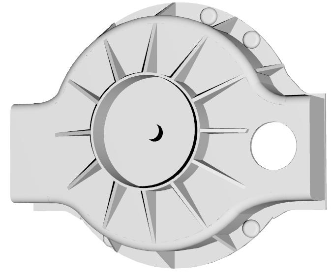
Considering weight savings, I think a new design might be in order.
In this case I've worked from the mounting holes to eliminate internal
stand-offs (except one) and most internal ribs - I feel a
lot of weight is in these areas.

Not dissimilar to the old design but a lot more critical in
designing the pattern because of very tight tolerances.

I feel this design is just a strong in fact might even be
stronger because the flange is both top and bottom and supports the MM
area both top and bottom. The actual mounting pad remains about 6".

I can carefully watch thicknesses to maintain the
 minimum, which will be about 4.5 mm.

The drawing is a bit rough but the dimensions are fairly accurate.

I would estimate about 9 to 10 lbs, that should be close enough for anyone.

George (down under)
I think this is a great idea George. Much much better than my original
concept. If you don't mind doing the pattern over. Better cosmetically
as well.

I added an idea.
Instead of using that great big 15 mm 180 mm diameter thick plate
in the center use a stiffening cylinder just a little larger than
Tracy's PSRU. The cylinder should be about 40 mm high.

Only a 15 mm thick  50 mm diameter slug of metal in the center
where the input shaft seal is located is all that is needed.

Also taper the ribs as suggested by somebody just a while ago.

And for good measure and the last little bit of weight saving
cast in the pie shaped holes between all the ribs. Not shown
in this illustration.

Good idea and good work George.

Paul Lamar

The AirCraft Rotary Engine NewsLetter.  Powered by Linux.
ACRE NL web site. http://home.earthlink.net/~rotaryeng/
Copyright 1998-2003 All world wide rights reserved.