Paul,

 In early August you suggested Paul Conner send his SQ2000
motor mount back,
suggesting it was going to fail. That engine mount looks like a
Conversion
Concepts mount. Care to elaborate?

Dave Wilenius
Cozy Mk4 #796
Conversion Concepts changes their design with regularity. I have not
seen the latest. If Joe Hull sends me a picture I will comment.

Paul Lamar
 Well Joe, how about it? I would think that the canard community would
be very much interested in this.

Dave Wilenius
Cozy Mk4 #796
You can see lots of photos on the web site:
www.conversionconcepts.com

Bulent
OK I will assume these are the latest.

Paul Lamar
First problem.
This problem jumped out at me when I just accessed the web site.

When they calculated the CG by NOT including the 8# starter and the 30# prop
the CG on the engine is further forward (pusher) than it is in a real
installation. This erroneously made the the four mount system that they
use look better than it really is. Very clever or dumb depending
on how much credence to their motivation you give them. The real
engine CG is further aft in a pusher installation. About where the
rear housing is located. Honest mistake? Perhaps!

Paul Lamar
OK given the actual CG of the engine/psru/prop combo at or
about the rear end housing here are some of the problems.
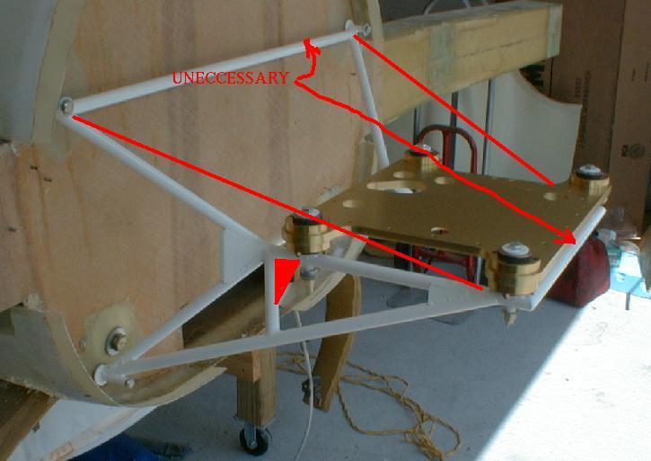
There is nothing wrong with a truss beam
if it is used in a single plane along with its support tube.
In this case the truss beam is rotated in at the top to accommodate
the unnecessary front mounts. Rotating a truss beam in this manner
results in super high compressive loads in the lower tube. If rotation is
continued the compressive load approaches infinity. If rotated 90 degrees
the tubes become simple cantilevered beams with extremely high bending loads
forward around the front mounts. Of course the mount will fail long
before that happens.
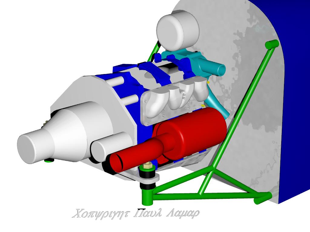
Here are some old pictures on this design and a Limo EZE illustration that
is similar. In the Limo EZE illustration the truss beam and its
support tube are in the same plane.
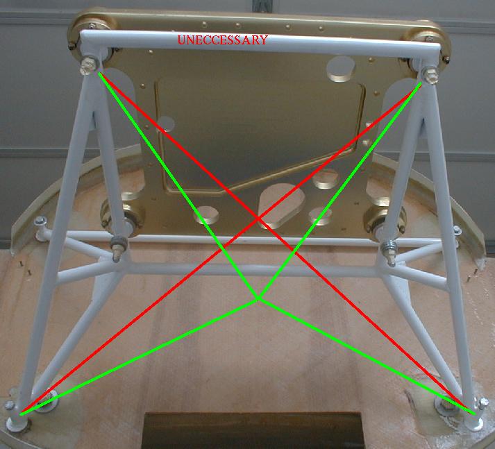
Second problem is: no lateral bracing.
There is no lateral support shown in the Limo EZE illustration either but
it could be provided by a ball jointed strut over to the spar or wing
in a pusher.
There is no rear mount shown in the Limo EZE but the loads are on the order of 180
pounds with a six G download so a simple vertical strut to the firewall with
rubber rod ends can handle those low loads. This would also allow adjusting
the engine thrust line angle for maximum speed and efficiency as done in
the Quest Air venture.
The main mounts under the engine/psru/prop CG combo take the roughly
1800 pound download from the six G pull up or hard landing. An aerobatics
airplane might see ten G's or 3000 pound download.
The sandwich plate looks wonderful but it is needlessly heavy or
expensive (when pocketed out) or both and is more likely
to cause oil leaks as now there are two oil pan joints
instead of only one. A Schertz Beam bolted under the rear
housing and oil pan is a far less costly and a lower weight solution.
That is also the solution the Mazda engineers choose for the 3rd gen RX7.
BTW somebody on here recently mentioned that a good space
frame is stable using rod ends (ball joints) at every junction.
No local bending loads at any joint. I don't think this design
would pass that test.
Paul Lamar
The AirCraft Rotary Engine NewsLetter. Powered by Linux.
ACRE NL web site. http://home.earthlink.net/~rotaryeng/
Copyright 1998-2003 All world wide rights reserved.

