First problem.
This problem jumped out at me when I just accessed the web site.

When they calculated the CG by NOT including the 8# starter and the 30# prop
the CG on the engine is further forward (pusher) than it is in a real
installation. This erroneously made the the four mount system that they use
look better than it really is. Very clever or dumb depending on how much
credence to their motivation you give them. The real engine CG is further
aft in a pusher installation. About where the rear housing is located.
Honest mistake? Perhaps!

Paul Lamar

OK given the actual CG of the engine/psru/prop combo at or
about the rear end housing here are some of the problems.

There is nothing wrong with a truss beam
if it is used in a single plane along with its support tube.
In this case the truss beam is rotated in at the top to accommodate
the unnecessary front mounts. Rotating a truss beam in this manner
results in super high compressive loads in the lower tube. If rotation is
continued the compressive load approaches infinity. If rotated 90 degrees
the tubes become simple cantilevered beams with extremely high bending loads
forward around the front mounts. Of course the mount  will fail long
before that happens.

Here are some old pictures on this design and a Limo EZE illustration that
is similar.  In the Limo EZE illustration the truss beam and its
support tube are in the same plane.

Second problem is: no lateral bracing.

There is no lateral support shown in the Limo EZE illustration either but
it could be provided by a ball jointed strut over to the spar or wing
in a pusher.

There is no rear mount shown in the Limo EZE but the loads are on the order of 180
pounds with a six G download so a simple vertical strut to the firewall with
rubber rod ends can handle those low loads. This would also allow adjusting
the engine thrust line angle for maximum speed and efficiency as done in
the Quest Air venture.

The main mounts under the engine/psru/prop CG combo take the roughly
1800 pound download from the six G pull up or hard landing. An aerobatics
airplane might see ten G's  or 3000 pound download.

The sandwich plate looks wonderful but it is needlessly heavy or
expensive (when pocketed out) or both and is more likely
to cause oil leaks as now there are two oil pan joints
instead of only one. A Schertz Beam bolted under the rear
housing and oil pan is a far less costly and a lower weight solution.
That is also the solution the Mazda engineers choose for the 3rd gen RX7.

BTW somebody on here recently mentioned that a good space
frame is stable using rod ends (ball joints) at every junction.
No local bending loads at any joint. I don't think this design
would pass that test.

Paul Lamar
Steve Brooks wrote:
Paul,
I am by no means an expert, and I'm confused by your staement.  I have this
mount on my Cozy MKIV, and whith the stock cowling, and Tracey Crooks's
PSRU, the prop hub extends 3" beyond the rear of the cowling.  This seems to
be a perfect position, and should not require any kind of prop extender.
The Lycoming O-360 requires a 6" entention, and several builders have
installed an 8".  In light of this, I don't unsderstand your statement about
the engine being further forward that it should be.

Also, the additional braces that you drew in the the photo in your other
email would not work in all cases.  I looked at my mount & engine, and the
passenger side would cut right through the exhaust manifold and/or turbo,
and the ones under the mount would not leave room for the radiator.

By the way, was your staement about the "real" engine CG reffering to a
Lycosaurus  ??? Surely not !

Steve Brooks
Cozy MKIV #1071
Are you thinking of the aircraft CG instead of the engine CG? When designing
a motor mount the position of the ENGINE CG is crucial to the design of the motor mount
regardless of the weight and position of the engine relative to the aircraft
CG. The loads on the engine mount only refer to how far the ENGINE CG is from
the firewall. Does this clear it up?

Here is an article on the subject from the ACRE NL web site below.
This has been on the ACRE NL web site for years.

_______________________________________________________________________
SUGGESTIONS FOR BUILDING A ROTARY ENGINE MOTOR MOUNT.

INTRODUCTION.

A good motor mount is critical in obtaining a good non aircraft engine
installation. It is easy to copy what has been developed in the aircraft
industry over the last 100 years if you are using a conventional air cooled
aircraft engine.

Rotary engines on the other hand are a whole new ball game. One must learn a
little bit about Statics and Dynamics. Both formal courses in mechanical
engineering schools. Motor mounts are in the category of space frames. Space
frames are made of tubing and the idea is not to generate any bending loads
on tubing if it can be avoided. Bending loads lead to cracks and eventual
failure.

You can learn an amazing amount about space frames if you make a
quarter scale model out of 3/16 inch square balsa sticks.  Apply some
typical loads and see what deflects and how stiff your model is. If you weld
you can also make models out of welding rod.

All of the members of a space frame should be in pure tension or
compression. Any loads applied to a space frame must be applied to a point
where three or more tubes join together, A solid bolted juncture of one tube
and a rigid firewall such as found on composite airplanes is also
acceptable.  Do not assume that this is the same as feeding the load into a
rubber bushing located on the firewall as being the same thing. This creates
local bending loads in the tubing and the bolt that goes through the
firewall. These bending loads must be accounted for by locating such a bolt
at the juncture of three tubes.

If these rules are violated the motor mount might still work but it
is nearly impossible to predict the stresses and deflections and therefore
these kinds of mounts are extremely dangerous. If you stick to the
rules it will be easy to calculate the stresses using simple graphical
methods and look up tables.

The CG of the combination of engine prop and PSRU is where most of the loads
are applied. The criteria I use is a six G pull up or a six G hard landing.
This is the worst case scenario and probably exceeds the design loads of
most aircraft.

When you drop the airplane in there is a huge download at the
engine/prop/PSRU of about 1800 pounds. Consequently the rubber motor mounts
should be located at or near this CG point. A minimum of two rubber mounts
are required. This is because the prop generates about a 400 foot pound
average reaction torque and one of the jobs the rubber mounts are called to
perform is to keep the prop torque from twisting the engine out of the
airplane. This CG rule is violated in air cooled engine mounts because the
mounting rubbers are widely separated vertically to take the cantilevered
bending moment the engine/prop combination generates when a hard landing
occurs. Unfortunately auto engines do not have this motor mount feature
built in. If they did it would be too easy.

The concept of load path is an interesting way to design any structure. For
every action there is an equal and opposite reaction. When a load is applied
to an airplane at some point, other than the CG, the load must get to the CG
of the mass of the airplane through the structure of the airplane. This is
called the load path. An examples of this is the common practice of storing
the fuel in the wings. The lift from the wing acts directly on the mass of
the fuel. This reduces the bending loads on the spar.  This is also the
reason the Questair Venture nose gear is attached to the engine and not the
airplane. Every rear engine race car built for the last thirty years feeds
the loads from the rear suspension directly into the engine and
transmission bypassing the chassis. Since the engine is a major mass in any
airplane design it pays to feed the loads generated near the engine directly
into the mass of the engine.

There is a torque reaction from the prop that is reacted by the gears in the
PSRU and thence into the PSRU housing through the motor mounts and then into
the airplane proper. If the rubber mounts are located on the adapter plate
between PSRU and engine, rather than the engine itself, that is the most
direct load path. It minimizes the stress on the bolts and spacers that
attach the PSRU to the engine.

The motor plate can take all the loads and incorporates the rubber bushing
motor mounts. It also directly takes the thrust load as well as roughly an
800 ft pound peak torque pulse applied to the prop from the gear box. I am
not exactly sure what the exact peak value as it is mitigated somewhat by
the rubber bushings in the torque isolator plate between engine and gear box
and the rotational inertia of the engine and gear box. Peak torque is
roughly twice average engine torque and average torque at the prop is up to
400 ft pounds. Two times engine average torque because of the 2.17:1 gear
box. Since the rubber bushing are about three feet apart they see only a 270
pound vertical pulse. If they were only one foot apart they would see the
full 800 pound vertical pulse and would need to have roughly three times the
travel for the same pulse absorption.

This is the main reason the Questair Venture is one of the smoothest
airplanes flying. It was designed by Jim Griswold of Piper Malibu fame and
Ed McDonald. BTW IMHO a major breakthrough in aircraft engine motor mounts.

The ideal motor mount brackets would be cast into the Mazda  front cover to
fit a Lycoming dynafocal mount. Since that is not practical right at the
moment the next best thing would be to have a cast bell housing adapting the
PSRU to the Mazda rotary engine. That too looks like it will not happen in
the near future so the third best thing is to have the PSRU adapter plate
modified to incorporate the rubber bushings motor mounts.

A third alternative is use what is called a Schertz beam. A special oil pan
is welded up with a notch under the rear (in the car) end housing. A beam is
then bolted to the engine using the oil pan bolts. This beam can take the
form of a one by two, 4130 .065 wall rectangular steel tubing or a tig welded
T beam made from 1/2 inch aluminum plate. It could also be made from
a thin 4130 sheet metal steel channel if it is braced up to the engine with
1/2 inch square 4130 tubing.

Build a full scale mock up of the motor mount design you would like to use
and all the major parts that are going under the cowl. This will save you a
year or more and from making many parts over and over again. You can also
use a good 3D modeling computer program such as Rhino or Solid Works.

See the drawings on the web site for various motor mount arrangements
based on these design principles.


BENDING MOMENTS, TUBE AND FIREWALL LOADS:

You are dealing with a 1800 ft pound bending  moment and a 1800 pound shear
load during a six G pull-up maneuver at the firewall. It is assumed the
engine/PSRU/prop weighs 300 pounds and the CG of the assembly is one foot
from the firewall. A hard landing will also generate these kinds of loads on
the firewall due to the mass of the engine system.

Some airplane designs, mainly the early Lancairs, had only one foot between
upper and lower motor mount hard points on the firewall. Consequently the
1800 pound tensile and compressive loads on the firewall due to the bending
moment can be halved or only 900 pounds if the distance between the hard
points on the fire wall are two feet instead of only one foot.  The shear
loads on the firewall will remain the same. This is advantages even if it
means adding new hard points to the firewall out near the fuselage skin.

It is best to spread the Barry rubber mounts as far apart as possible. This
minimizes deflection in the rubber so softer rubber can be used which
maximizes its ability to absorb engine vibration and torque.

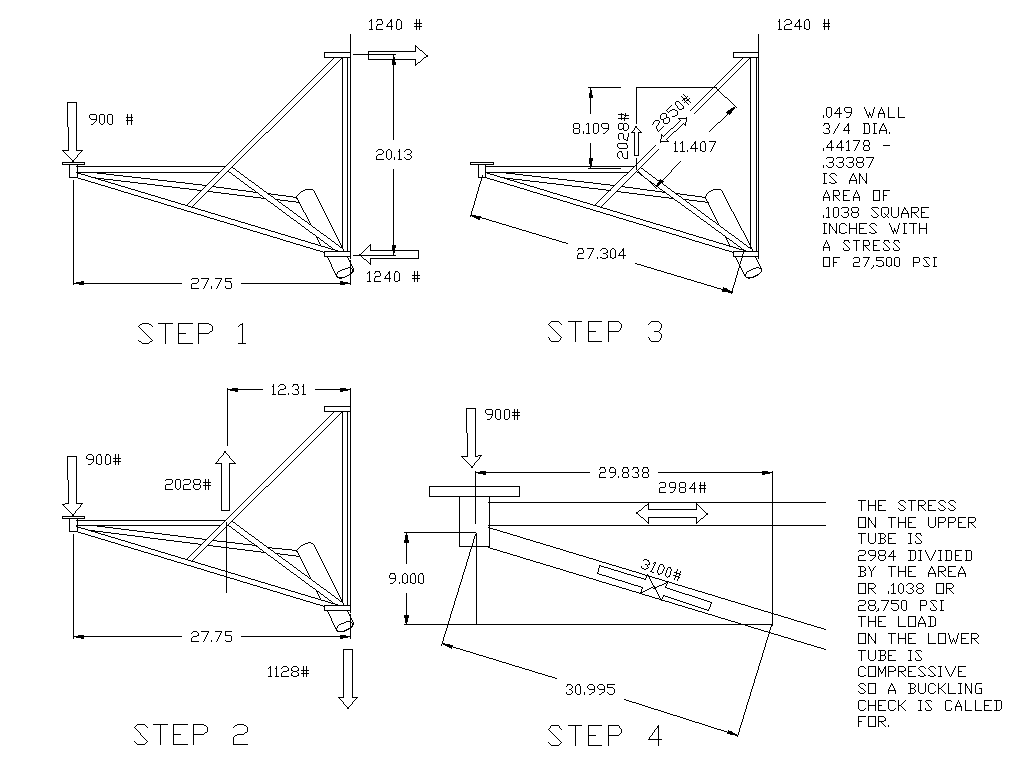
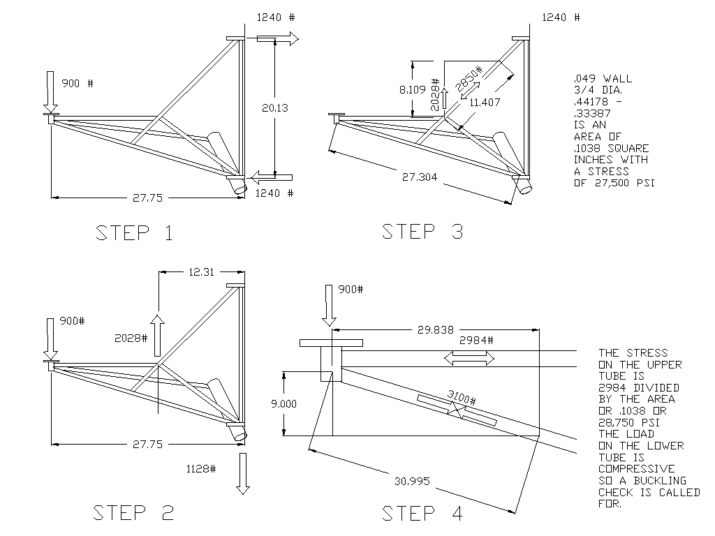
HOW TO CALCULATE THE LOADS IN THE MOTOR MOUNT TUBES.

See the tube load drawing on the web site. Make a scale drawing of the motor
mount. Top view and side view.

Step 1. If the tubes are tilted in when looking down from the top of the
motor mount rotate them so they are parallel with the airplane center line.
The side view of the motor mount should then reflect the true length of the
tubes. We are just going to determine the loads in the two critical tubes
on only one side of the motor mount.

Step 2. Multiply the distance out from the firewall to the rubber mount
times 900 pounds or half the load from the engine during a six G pull up.
Divide that number by the distance between the upper firewall mount and the
lower firewall mount. Draw arrows on the side view that are to scale. In
other words if the load is 930 # the arrow should be 9.30 inches long. Use a
machinist scale marked off in 1/100 of an inch. Notice the bottom tube
pushes in on the fire wall and the upper tube pulls out of the firewall.
Notice also that the firewall pushes and pulls back :-).

Step 3. We will do the bottom tube first. Move the arrow out to the end of
the tube and draw a right triangle. The length of the diagonal line is the
compressive load in the tube. In this case it is 974 pounds. Usually this is
the most critical tube due to a phenomena called buckling. We will talk
about that next. The length of the short vertical line is the vertical load
on the fire wall where this tube is bolted to. In this case it is 270
pounds for the lower firewall mount.

Step 4. Move the upper arrow out to the end of the upper tube. Draw another
right triangle. Again the length of the diagonal line is the tensile load in
the upper tube. In this case it is 1123 pounds. The length of the vertical
line is the vertical load on the firewall imparted by this tube. in this case
630 pounds. Note that 630 pounds and 270 pound equals 900 pounds.

Paul Lamar

CALCULATING THE STRESS IN THE TUBES AND CHECKING FOR BUCKLING.

Written by Bill Freeman:

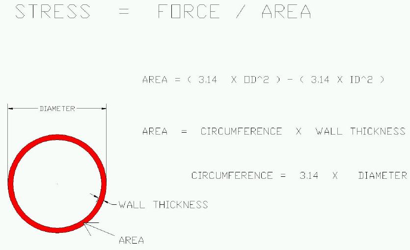
Once you know the force that the tube will have to support (along its axis),
you can calculate the stress in the tube (which is the design limit) from:

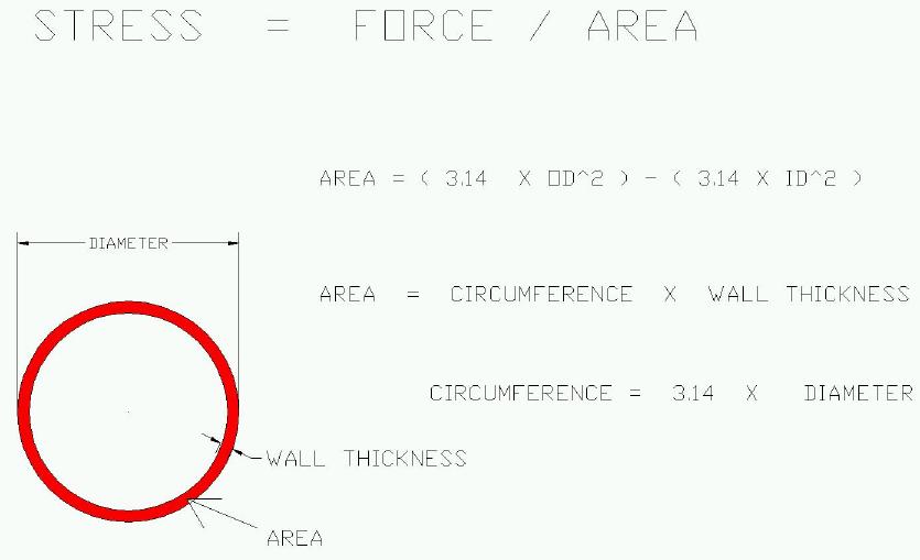
         stress = force/area             where the area is the

cross sectional area of the tube.  So calc the area for the outside diameter
circle

       area = PI * r * r        or  3.1416 * outside radius squared

then subtract the area of the inside diameter circle, same equation, but use
the inner radius.

You want to keep the tube stress below the yield of normalized 4130
chrome-moly steel which is about 66,000 psi.  I would suggest a 10 G landing
as the design point for the engine mount.  Paul used six G's above but
you can use ten G's if you want the motor mount to survive a minor crash.

If the stress is too high, use a thicker wall or larger diameter tube to
increase the area which will reduce the stress.  This is all there is to it
for a tube in tension.  NOT SO SIMPLE for a tube in compression since it
will possibly fail due to buckling.

Take a plastic soda straw and pull on it as hard as you can with your two
hands.  Can't break it, can you?  Now push on the ends with your thumbs -
pretty easy to crumple it up, huh?  This is buckling, which is a lateral
(sideways) instability in a long skinny member under compression.  Long
skinny structural members can fail in buckling WAY below the yield stress
tensile load.

The simplest thing to do about buckling is to use a relatively large
diameter tube to give a stronger lateral stiffness.  You can go look in std
eng tables, or if there is enough interest I'll do a short ' how to' on
basic buckling calcs.  But, if you use a relatively large diameter tube and
decrease the wall thickness to keep the cross sectional area in bounds i.e.
not too heavy, you will be more buckle resistant.  Also, a center brace,
even with a *very* small brace tube, will dramatically increase the
buckling resistance, because it cuts the effective length of the tube in
half.  Remember, buckling only happens in tubes in compression.

 Bill


Written by Paul:

BTW the bible for this sort of thing is Analysis & Design of Flight Vehicle
Structures by E.F. Bruhn et. al. Tri State Offset Company 817 Main Street
Cincinnati Ohio 45202 Published in January 1965.

I am sure Dick Van G keeps a copy along side his drawing table or computer. I
paid $14.75 for my copy 30 years ago but I'll bet it is well over $100 now.
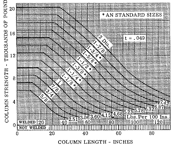
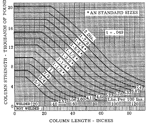
Well worth it however. Plenty of buckling tables for both 4130 and aluminum
tubing both round and streamline. See the one on the web site.  bucktube.jpg

There is also a very good chapter on aircraft loads with lots of worked
examples. The book reflects the distillation of 65 years of experience with
aircraft structures.

FABRICATING YOUR MOTOR MOUNT.

Drill holes in a thick steel plate, bolt down the original mount, remove
any tubes that need to be removed, heli-arc  weld on the new tubes and
send it out for normalizing and re-heat treat. Then re-ream the bolt holes.

One can also build a motor mount welding fixture out of large steel
tubing.

STATIC TESTING YOUR MOTOR MOUNT DESIGN.

Static test your motor mount by using the airplane as a jack to pick up the
front of a front engine car. The average front engine car weighs about 3000
to 3600 pounds so half to two thirds of that is 1500 to 2000 pounds. Your
static weight target load for the complete motor mount is 1800 pounds. It is
hard to come up with that much dead weight other than a car. You would have
to buy 36... 50 pound bags of cement and then find enough room to hang those
bags off your motor mount so use your car.

Don't worry about the download on the horizontal stabilizer. If it won't take
about 700 pounds down force it won't survive a six G pull out either. Apply
the force mainly to the stabilizer spar near the point where it intersects
the fuselage. You can distribute some load along the spar if you need help.
BTW this in effect is static load testing the entire fuselage and landing
gear. Don't try to static load test the motor mount to ten G landing loads.
You will probably fail something in the fuselage or the stabilizer.

Paul Lamar

___________________________________________________________________________


The AirCraft Rotary Engine NewsLetter.  Powered by Linux.
ACRE NL web site. http://home.earthlink.net/~rotaryeng/
Copyright 1998-2003 All world wide rights reserved.