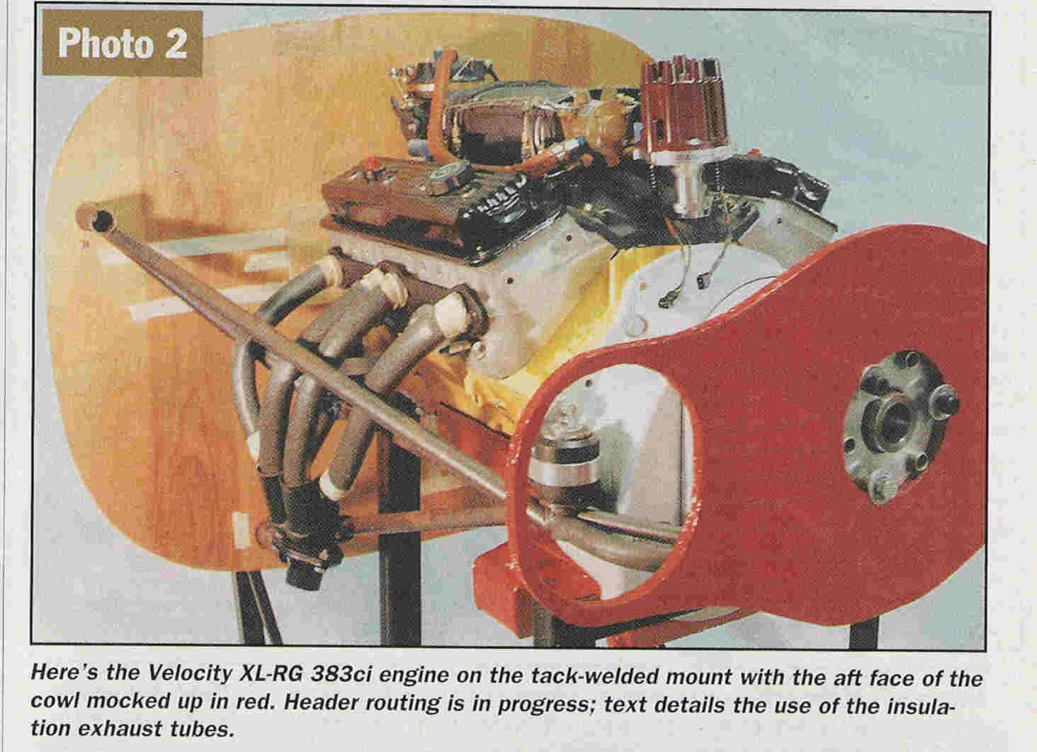
This came from an article in Nov. Custom Planes called
V-Engines for High Performance Aircraft by Len Bechtold.

At first glance to the untrained eye this mount looks plausible.

It appears however the designer is underestimating the load
on the two aft rubber bushings. A spur gear box for a 350 hp
383 ci inch Chevy small block V8 is going to weigh in the
neighborhood of 75 to 100 pounds so the engine/psru/prop
CG will be far aft of the center of the engine. My guess
it will be around the rear set of cylinders. There is nothing
wrong with four motor mounts but the aft two will take
probably 80% of the load. My guess the weight of this
engine/psru/prop despite the aluminum block will approach
550 pounds. 80% of that is 440 pounds so each rear
mount is taking about 220 pounds static. Not counting
prop reaction torque.  Looks like he might
want to go up a size on those Barry rubber bushings.
These are the same type of Barry rubber bushings used
in the Questair Venture and the same types as I am
suggesting for our use.

There appears to be a bent cross tube that goes around
in front of the psru. This tube is not doing much and could
be eliminated if the aft rubber bushings were lowered
and moved outboard so an X member could be installed
under the oil pan to provide lateral support. As shown
in this picture there is little lateral support other
than that provided by bending in the tube ends.
This could lead to cracks in the tubing joints.

Also my guess is the lower tubes are a bit on the small
side for buckling reasons at a 6G download.

The forward mounts also need to be stabilized by an X member.

As I stated on here many times before make a 1/4 scale model.
If you make a model and a apply scale loads design errors of
this nature will become immediately apparent.

Do not assume the rubber bushing somehow provide joint
stabilization. That is a common error. Assume the rubber
bushings are not there when analyzing a mount.

Each loaded joint must be located by three or more tubes.

Assume all the joints are made with pin joints, ball joints
or rod ends. This eliminates all local bending loads on tubes
ends.

Motor mounts can be designed to utilize the bending strength
of tubing but it is beyond my capabilities to calculate
the stresses and predict the life of the mount.
This has been done in in several production aircraft
mount designs but years of experience with these mounts have been
accumulated and design changes have been made and gussets added
over the years when cracks developed. Very small changes in these
type mounts can have major implications as far as local bending
stresses in the tubes are concerned. It is best to design the
mount using a pure ball jointed space frame simple approach. The
probability of achieving a safe, crack free motor mount
is much higher right from the get go.

Paul Lamar

The AirCraft Rotary Engine NewsLetter.  Powered by Linux.
ACRE NL web site. http://home.earthlink.net/~rotaryeng/
Copyright 1998-2003 All world wide rights reserved.