Paul and group:

We recently evaluated several options for Glass Goose motor mounts.  The
feedback was very much appreciated.  Using the 1 forward, 1 aft and 2 middle
mounts can be done, but appears to have the following disadvantages:
1. It is necessary to fabricate 2 new center engine mounts, as well as one
forward and one aft mount.  The original center-housing engine mounts are too
wide to fit inside the limited-width pylon.
2. Building 2 bridges between the pylon walls is required.  This is difficult
because it is a very tight space and lots of the glassing needs to be done
upside down.  It also adds aft weight, and uses a relatively unsupported aft
bridge for a lot of the load.

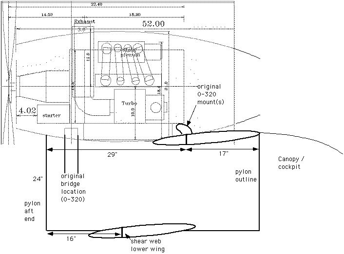
With your indulgence, I would like to explore once more the concept of using two
mounts on a single bridge in the rear of the pylon, which would handle all of
the aft weight in this pusher configuration.  I'll still use a 12A/early 13B
front plate for 1 (or two lighter) front mounts.  In testing this concept, I
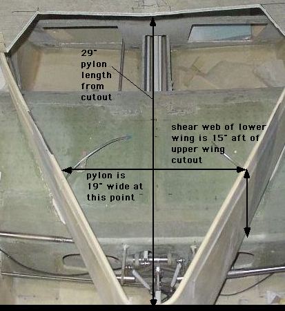
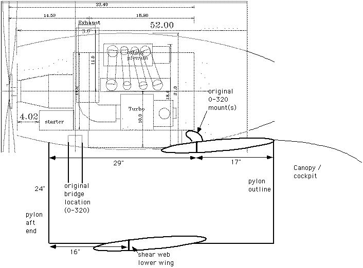
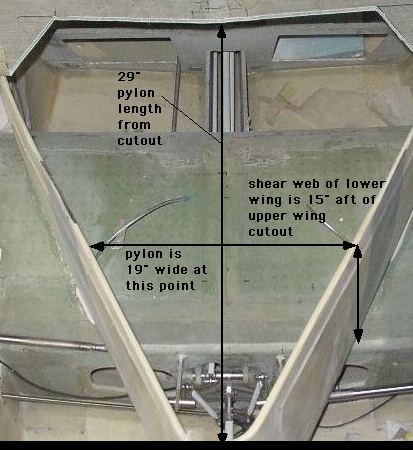
built a single-bridge test specimen.  This bridge leans aft about 15 degrees,
using the structure of the lower wing shear web for vertical support.  I built a
calibrated hydraulic press to deliver a vertical load on the bridge in the area
of proposed mounts.  Static loading of this test specimen to almost 3,500 lbs.
showed only minimal flexing of the wood/glass structure with no signs of
failure.  So this structure appears more than strong enough to handle the loads
of an aft mount.

If this bridge is located at the aft edge of the engine block, there is about
15" in width to work with.  This means that any mounts would have to be below,
not beside, the engine block.  Going aft even a few inches back to the redrive
mount plate unfortunately narrows this distance rapidly.

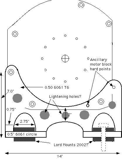
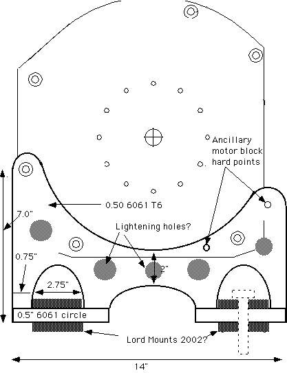
My questions today revolve around whether a (modified Scherz?) beam bolted to the
aft engine block and bridging down to motor mounts below could work.  Paul's
suggestions of using 1/2" 6061 T6 x 2", combined with Bruce T's ideas are
incorporated into the attached sketch.  This method would require shortening two
of Tracy's redrive spacers to make room for the 1/2" wide mount. It would also
require adding one or two more mounting points on the "bolt-deficient" side of
the engine.  Bruce suggested a rear housing dowel, and there is also an ideal
area to weld on a small angle plate on this side of the rear housing.  These
extra hard points appear easily feasible.

The draft sketches of this beam mount show a minimum of 2" in vertical height,
and use two, centered horizontal mounting plates for the Lord mounts on each
lower side.  These would be roughly circular in shape.  In order to get the
Lord mount bolts up far enough to clear the bridge support structure, a small
span opening over each Lord mounting plate of 2" in height is required (there is
very limited access from below).  This allows both sides of the Lord mounting
plate to be supported, which may not be necessary (based on Paul's redrive mount
design).

My specific questions are:
1. Is this general layout a reasonable compromise between an ideal redrive plate
mount and the other options?  Its cost, ease of building and weight savings seem
like advantages.  I'm sure that I'm missing some disadvantages.
It would be easier to make and stronger if you could move it back 2.5 inches and
integrate it with the existing 1/2 inch thick Tracy motor plate/psru adapter.
You could weld on that or make a new one.

Since the front mounts, using the 12A front cover, will react most all of the prop
torque the rear mount can be only one large mount or two closely spaced mounts
as shown here. I assume you mean Barry rubber bushings when you say "Lord mount".
2. Do the Lord mounting (horizontal) plates need support on both sides (in the
drawing, a 0.75" outer "arm" was arbitrarily chosen)?  Is the proposed support
adequate?
- if this is overkill for the support, could each 1/2" Lord plate be supported
only on the inboard side as with Paul's KIS mount (this would allow moving each
mount 3/4" outboard).
Yes that will work. There is enough bending strength in the 1/2 inch thick 6061 T6
plate to allow cantilevering the rubber holders, by in essence, only one inch.
The horizontal plate should then be just one piece.
3. Paul mentioned that a TIG-welded 1/2" 6061 T-beam is one option.  In this
configuration, would welding of the Lord plates be preferable to AN-4 bolts?
I've read that welding drops the strength of 6061 from 20K ksi to about 8K ksi.
 If welding is used, should the structure be heat treated to recover some of its
strength, or is the 8K ksi strong enough?
You don't need to worry about that. The stresses in the weld area would be
well below 8,000 psi in this design. You could also drill and tap the vertical
plate from the bottom and bolt the horizontal plate on. Use 3... 5/16th course thread
bolts. One in the center and one on each end about 3/4 inch in from the edge of
the vertical plate. This assumes the front mounts are at least 18 inches apart.
- perhaps there is a better method to mount these 90-degree horizontal Lord
plates to the main mount (such as bolted, 90-degree brackets, etc.)???
4. Provided that this whole concept is evolving toward a solution, are
lightening holes appropriate in this type of structure?  If so, can Paul or
anyone make suggestions as to how large they might be (I've heard the rough rule
of 1/2 the width of the structure but don't want to err on this critical structure)?
Unfortunately you are not going to get much weight out with lightening holes.
Probably not worth the effort of cutting them. 0.16 pound apiece for a two
inch hole in 1/2 inch thick aluminum plate. But they will not hurt the over
all strength.
5. If the vertical and lateral loads of this structure are adequate, are there
any fore-aft or twisting loads that need to be addressed?  I could add two,
bolted, angle plates from the main mount to the outer oil pan bolts, or some
type of vertical strut if necessary.
There will be some twisting (pitching) loads about  a lateral axis due to the prop thrust
center line being 7 or 8 inches above the rubber mounts but these are reacted
by the roughly  18 inches  for and aft distance between the front and rear mounts.
Not to worry there. The rear mounts are actually unloaded in this circumstance.

The axial twisting loads are from the roughly 400 foot pound prop torque reaction
loads.  Since the mounts on the 12A front cover are hopefully  more widely spaced
than these mounts they will react most of the prop torque.

BTW I just got some more info on the RX8 rubber mounts. They are 28 inches
center to center. Almost as far apart as the mounts on my KISS Cruiser :)
Perhaps there are some Mazda engineers on here after all :)
6. I noted that Paul's motor plate mounts, which should be slightly less loaded
than these, specify the 2002 series Lord mounts.  These have several versions in
the charts.  Should the Lord mounts for this proprosed structure be in the
240-lb range of the 2002 or 2003?  Obviously a front single (or pair on each
side of the 12A cover beam) would carry much less load.  Maybe a 100-lb 2002?

Thanks again for ideas, comments and suggestions in this part of my project.

Scott Gettings
Does Lord also make a 2002 rubber bushing or is that a Barry part number?

The rear mounts will take 90 percent of the static vertical load
so they should be rated  around 150 pounds each. The front mounts
should be about the same as they will react most of the prop torque
even though the static load is only about 50 pounds total or 25 pound
each. Make sure you spread them widely. At least 18 inches.

Paul Lamar

The AirCraft Rotary Engine NewsLetter.  Powered by Linux.
ACRE NL web site. http://home.earthlink.net/~rotaryeng/
Copyright 1998-2003 All world wide rights reserved.