Paul and group:

We recently evaluated several options for Glass Goose motor mounts.  The
feedback was very much appreciated.
<<<<< BIG SNIP >>>>>>>>
Thanks again for ideas, comments and suggestions in this part of my
project.
Scott Gettings
Does Lord also make a 2002 rubber bushing or is that a Barry part number?

The rear mounts will take 90 percent of the static vertical load
so they should be rated  around 150 pounds each. The front mounts
should be about the same as they will react most of the prop torque
even though the static load is only about 50 pounds total or 25 pound
each. Make sure you spread them widely. At least 18 inches.

Paul Lamar
Paul,

Thanks a million for all the comments.  Yes, you are right, I meant Barry,
not Lord mounts. Duh!

The only thing I wasn't clear on was about using 5/16" bolts tapped
vertically into the 1/2" plate.  Will this leave enough metal around the
threads since the plate is only 1/2" thick?

I'll be working on this version and hopefully the next pictures will show
some real progress!

Scott Gettings
I think so but 1/4 inch bolts will also work. It is mostly compressive
loads between the motor plate and the horizontal plate. You could also
use some 2 1/2" by 2 1/2" thick (1/4")  wall extruded Al angle and merely bolt
it to the bottom of Tracy's motor plate. Thicken it up to a 1/2 inch
where the rubber bushing holes go. Industrial Metal Supply in Burbank
CA has a web site and they will ship nationwide.

You might have to move the starter by welding on a piece of 1/2 on
the side of Tracy plate.

Paul Lamar
The angle plate bolted to Tracy's motor plate might indeed work, as I
could aim the flange away from the plate and gain a little
pylon width.  I'll check this out as well.

Thanks again,

Scott Gettings
You could also use some smaller angle front side and back side and
just bolt the Schertz beam to the plate with a bunch of bolts.

Paul Lamar
Hmmm.  This is VERY interesting and would fit in the Goose pylon.  Is it OK to
assume that I could make a "U" channel using two, 0.25" 6061 angles, say 2 1/2"
(horizontal) on one side, with sufficient vertical (maybe 3-4") on the other?
In order to get the mounts low enough and get to the bolt holes, one side of the
angles will need to have a vertical height of at least 3-4", which are readily
available.
So one angle bar would be bolted to the block and the other to Tracy's plate,
"sandwiching" Tracy's spacers.  If the horizonatal parts of the angles
overlapped, they would be 1/2" thick, which would fulfil the need for the Barry
mount plate thickness without adding other material.  The horizontal overlaps
could bolt together in the center sections if necessary.

Sorry to say I don't have Tracy's redrive drive yet.  Is the distance between
the redrive plate and the block (the spacer length) precisely 2.5"?  I can get
this measurement from Tracy if it not handy; but his site doesn't have detailed
redrive drawings.

Thanks again,

Scott Gettings
I am not sure I follow you here. If you send a sketch I can knock out a 3D.
The distance, as I recall, is 3.050 inches.

You can also buy 3" inch high channel 1-1/2" wide flanges  1/4" wall.
http://www.spicerindustries.com/metal/alumangle2.html

You could shim this to 3.050 and use it as a combined PSRU plate
spacer and as a Schertz beam. You would have to thicken it where
the rubber bushings go. You could also slot it for ring gear
clearance if necessary. I think even Tracy would like this idea :)

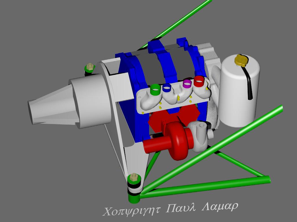
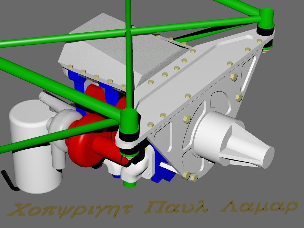
Here is a similar idea.

Paul Lamar

The AirCraft Rotary Engine NewsLetter.  Powered by Linux.
ACRE NL web site. http://home.earthlink.net/~rotaryeng/
Copyright 1998-2003 All world wide rights reserved.