<<<<snip>>>>>>
Can you get 6 by 3 by 1/4 extruded angle?
http://www.spicerindustries.com/metal/alumangle.html
I see 6 by 4 by 3/8 at 4.2 pounds per foot.

This type of mount so stiffens the attachment between the engine and
the PSRU plate that you can just use a spool on the left bolt.
No need to cut the spacer. This part would have universal use
as we could make long ones and people could cut them off as needed.

It is nearly impossible to bend 1/4 inch plate with
flanges much deeper than about 2 inches with a 3 inch wide channel.
It must be done on a large and powerful press break and that is just
the way it is.  Can you move the starter to one side and raise
the bridge for the rubber bushings?

You could use more than two bolts on to fasten the the motor plate to
the channel if you wished. The two existing ten mm bolts would be fine however.

You can always make your design out of separate pieces of 1/4 inch Al plate
and tig weld them together. If you do that you will need a couple
of ribs inside if it is 6 inches deep. Seems like a heavy way to go.

You could also just bolt a bracket to Tracy's plate around and
underneath the starter.

Paul Lamar
Ops forgot the drawing.

Paul Lamar
OK, thanks much.  I understand the strength requirements and will
pursue one of these options.  Maybe bolting a bracket under/around
the starter (1/2" angle, I assume) as you suggested might be easiest.

Scott Gettings
It is only seeing up load or down load. The front two mounts will
react most of the thrust and torque.

Paul Lamar
OK, thanks once again.  Studying the necessary measurements today,
it looks like the bottom of the engine block has to be about
4" above the highest point of the bridge structure in the pylon.
This is because the thrust line has to be high enough for the
prop to clear the lower tail structure.  The walls of the pylon
are about 4" too short to have the bridge high enough without
adding to the pylon walls.

I have found some sources for 5"-6" 6061 angle and "Z" extrusions,
which would give me the necessary vertical spacing.  Most of
these are 1/2", but some 3/8" and 1/4" thicknesses may be available.
I understand that some extra braces will be required if I
use 1/4" angles or "U" that high.

Perhaps there is yet another alternative to the "height" problem.
One of your 3-d drawings showed a simple, flat Scherz beam
bolted to the bottom of the engine block and to Tracy's motor plate.
This concept would  be very easy.  However, a flat plate
bolted underneath from both the engine and motor plate would
require pulling the engine to remove the redrive.  But, using a
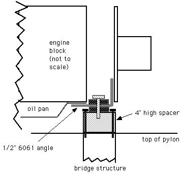
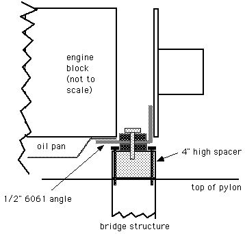
4"x2" 6061 angle bolted to the motor plate might work (see sketch).
 However, I would still need a 4" spacer from the beam down
to the bridge to take care of the height problem.  Would  it
make sense to use the simple horizontal beam as per your drawing
and make two 4" columns for spacers?  Maybe 6061 or 4130 3" round
or rectangular tubing with a flat plate welded on each end?  I
could run the Barry mount bolt all the way through, or use smaller
bolts (e.g. four AN-4s) to hold the spacer to the bridge
(easy if a 3" square column was used).  This concept would
keep the engine high enough yet stll allow using a very simple
Scherz-type beam.  I'm certainly guessing here, as I don't
know if this makes sense from a structural perspective.

Some of these versions would require building new oil pan.
If I'm going to use a 12A/early 13B front cover with engine mount
holes, I'll have to make a new oil pan anyway.  Is 1/8" 6061
satisfactory for a fabricated oil pan or is a thinner gage OK for
this part when it has no structural loads?

The front mount is the last concept to iron out.  I know the
rear mounts will absorb most all the vertical loads and you
suggested the front mounts should be at least 18" apart.
The width is not a problem, as I have plenty of space up front.  What
structure do you suggest for this front beam since it will
take both thrust and torque but not much vertical load?  Would a
4"x3"x1/4" angle with the vertical bolted to the engine and
the horizontal supporting the Barry mounts be adequate?  Or perhaps
a 1/2" x 3" vertical 6061 beam bolted to the front cover with
outboard, horizontal Barry mounts attached as per your KIS motor
plate design?

With two horizontal (narrowly spaced) rear mounts, is the ideal
thrust+torque configuration for these front mounts level and
horizontal, or should they be angled out (as in the car) and/or
forward by some degree?  Since I'll build the composite mount
into the wing, I can create them in any location or angle desired.

Scott Gettings
That will work too assuming you can get 4 by 4 by 1/2 inch angle.

I would use 4 inch high 1/2 inch plate for the front mount assuming
you have a 12A front cover.

Straight up and down will work fine for the front mounts.

Paul Lamar

The AirCraft Rotary Engine NewsLetter.  Powered by Linux.
ACRE NL web site. http://home.earthlink.net/~rotaryeng/
Copyright 1998-2003 All world wide rights reserved.