"Robinson, Chad" wrote:
Does the heat output scale linearly with the number of rotors?
That is, is the cooling challenge for a 20B exactly 150% of the
challenge for a 13B, or are there other issues related to the heat
density, maybe obstructions to the flow of coolant or oil,
or anything else like that here?

Thanks,
Chad
Directly proportional to HP. Lots of ducting issues. The obstruction
behind the radiator are more critical than the inlet duct because
everybody intuitively  understands an inlet duct for the most part.

Paul Lamar
Do you just convert the HP into watts to figure out how much heat to
disapate?

Does 100 hp = 65 kw watts...ballpark?

Phil
Basically yes. 746 watts = one HP.

Engines have what is called a heat balance. You can take a gallon fuel and
divide it
up. 25 to 30% as mechanical energy out, 35 to 30% into the cooling
system and
50% out the exhaust in the form of waste heat. Here are a few heat
balances
for different engines. Also go on the web site below and read the cooling
article.

Paul Lamar
Paul,
Can you give some guidelines on how to determine the size radiator needed
for a given amount of btu's.  I know it will vary depending on core
thickness, airflow, gpm, etc.  So, how does one figure out how much
radiator is requried?
Mark S.
Easy. Most people use about 600 cubic inches of rad volume on average for
a 13B :)
That number will drop in the future as we learn how to get the air in and
out of
the rad more efficiently. It will also drop when more people start using
thinner
cores IMHO. That is the direction of the auto and truck industry.

On the other hand larger core volumes can compensate somewhat for
bad duct design and too thick rads. That is the usual sledge hammer
approach to inadequate cooling.

So far nobody has complained about over cooling :)

IMHO Perry Mick is at the leading edge of air duct design and now
appears to be the most successful. He has a relatively tiny water rad in terms
of core volume. It could also be attributed to his ducted fan so
until we get more data from conventional airplanes he is the leader.

Also IMHO at the current time there are too many unknowns to use a
mathematical solution. It would help if more people would measure
the air and water pressure drop across their rad and the temperature
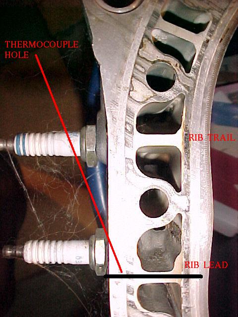
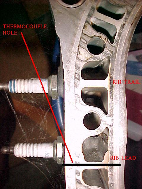
of the water going in and coming out of the rad. Another factor is the
temperature of the metal within 2 mm of the combustion chamber
in the area of the lower spark plug. The temperature of the water
is not the whole story.

Paul Lamar
Per your instructions, I drilled small holes in the webs (one per housing)
directly next to the leading plugs on the housings on my 20B for
thermocouples.  Now if I ever get off the ground...   BTW, what temps are
considered "within normal operation temps" at this location?

Mark S.
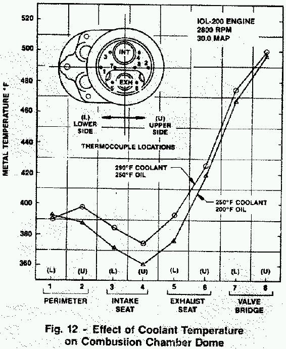
Something less than 500 degrees is considered safe for aluminum adjacent
to the combustion chamber. In the case of the Mazda rotor housings with its
mechanically bonded steel liner a higher temp could be acceptable.
This addresses the issue of transfer of heat between the metal
jacket and the coolant.

Here is some data from SAE Paper # 871042  Design and
Development of the Voyager 200/300 Liquid Cooled Aircraft Engine by
R.E. Wilkinson. Twenty pages. Published in 1987. This paper is about
the engine used in the Rutan Voyager around-the-world un-refueled
record holder.

The numbered thermocouples are within a few mm of the combustion
chamber surface.

Here also is some data from Mazda. 210 C is 410 F
I am not sure what the engine HP level was related to this data but I suspect
it is only around 160 HP.

Paul Lamar

The AirCraft Rotary Engine NewsLetter.  Powered by Linux.
ACRE NL web site. http://home.earthlink.net/~rotaryeng/
Copyright 1998-2003 All world wide rights reserved.