"..." wrote:
Thanks,
Mark
Sure. That should work fine. You need a short section of no threads
to take the shear loads.

Paul Lamar
Paul,
What about the bending loads on the bolts - would they take it !?
George (down under)
What bending loads? There are no bending loads on the bolts/pinion shafts.
Each bolt/pinion shaft is in single shear. In fact if you wanted
a belt and suspenders approach there is room for six additional drive
pins between each bolt/        ( pinion shaft on the planet carrier.)

     Q ,  How would extra pins between pinions help?

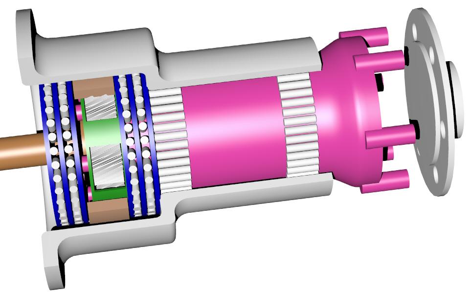
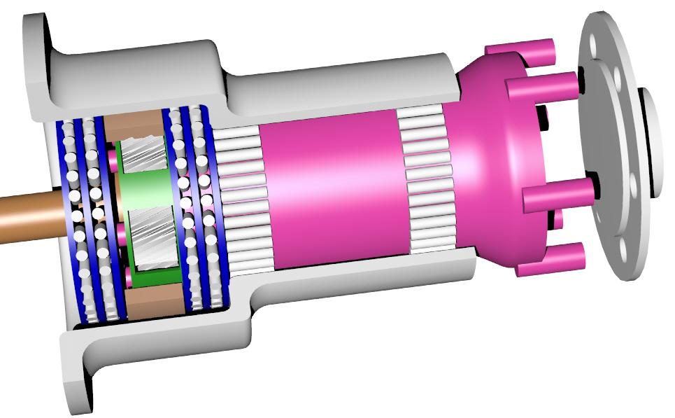
Here is a slightly different housing using the same idea done by Butch.
It is a bit clearer than my illustration on the web site.
The shaft concept is by Bill Jepson.

    Q    Where is the thrust bearing?

    Q    How is the trust load transmitted to the hollow shaft?

   the shaft  will need a flange on the planet carrier end

The tube shaft with flanges is what I had in mind, I had sketched a number
of versions out, similar to Bill's last weekend, before I had seen his
concept, much simpler to make.
It will be very important to get the pinion shafts lined up
correctly,otherewise the pinions will
be running out of line, giving only point contact with shaft and outer gear
housing.
I don't think there would be much chance of getting any pinion shafts in
line if they were welded
in position.
I have an idea for the thrust collar but need some dimensions of pinions etc

Geoff
Geof, Here is a somewhat better illustration of the idea with color
to make it clearer. Parts are still missing like the prop shaft oil
seal and prop shaft hardened steel needle bearing races.

Paul Lamar

The AirCraft Rotary Engine NewsLetter.  Powered by Linux.
ACRE NL web site. http://home.earthlink.net/~rotaryeng/
Copyright 1998-2003 All world wide rights reserved.