Butch,
Very interesting indeed, somewhat different to my own concept, but certainly
the basics are similar to my latest solution especially in regard to the
side MM's, although I've got my starter at o'clock and have my MM smaller
i.e. 150mm (see attached photo)
******George, the difference in MM pad height is .591" (15mm), which in our
case proves to be beneficial since it will allow the MM bkt mounting bolts to
be further away from the MM's resilent cluster and allow it to be tucked in
tighter against the MM bkt resulting in a a shorter MM arm.
Why have you cut the bottom-off  the flange -doesn't it add stiffening and
stress transfer !!?
******Not really George, it's considered "Air Gapped" and it's just dead
weight...The stiffening is amply provided for by the Flange's corner radius
and wall thickness, stress transfer remains intact and is still dissipated by
the engine mounting face in essence there's no change in dynamics. (Reffer to
side view)
I've had a lot of trouble getting 2nd hand starters and have opted for a
Turbo starter as all Aussie imports are Turbo the non-turbo are impossible
to find.
I find the Turbo has a smaller foot-print and therefore takes up less room,
can you include that as an option !!?
I can send the details to you if you wish !
******Absolutely George, please do!!!, especially since smaller is
better :) .....After-all this is a Yankee/Aussie Joint Venture, plus I don't
see any problem what-so-ever fitting it in as I expect it to be smaller in
distance between mounting holes than Tracy's 5.512" (140mm) ....IF at all
possible please send it to me directly before you leave on Friday, this way
I'll have a welcome home present when you return :)
Speaking of....I don't show a footprint for Tracy's Starter as I don't have
access to one to extrapolate info from, could one of you guys that have one
handy, post a dimensioned sketch so I can check for possible problems...Need
only 2 volunteers (Just to double check) for this, and please immediately
post your acceptance of this undertaking in ACRE so as not to jam Paul with
excessive e-mails.
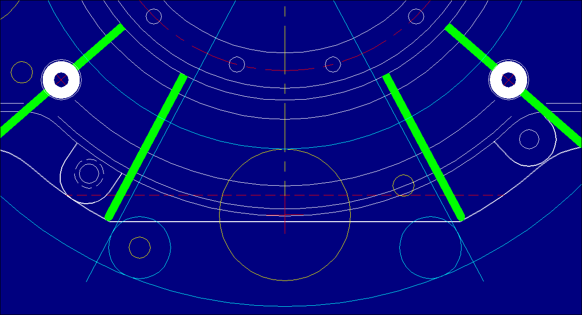
The stiffeners near the mounting bolts are very close- I found I had to move
them a bit in the prototype to allow sufficient room.

Why are the two at the extreme bottom sides - is there a strength issue
there, I thought 2 at the sides and one in the middle would be enough, that
way we could move them away from the mounting bolts,
giving a little more room to move.
******You've got Good eyes George, I wouldn't have caught it, since the
standard Flange Head 10mm, 8 grade bolt fits nicely (See Bolt Clearance-1)
FIXED already (See Bolt Clearance-2)

******A picture is worth a thousand words, 2 of them side by side, UMTEENTH
more (See attachment "Comparison").....Esthetically the one on the right
looks Heavier and much more Robust doesn't it?....The Bellhousing on the LEFT
is in what I call "The GREEN Phase" (Before structural analysis), the one on
the RIGHT I call "The RIPE Phase" (Profiled), as it reflects the
strengthening of the weakest points of the previous....And amazingly, all it
took was one add'l WELL PLACED Fin (Which was a trade-of to the piece I
removed from the bottom of the Flange), and obviously, the mirroring of the
Tripod Pads....This resulted, in the one on the right being more Rigid and
Stronger WITHOUT any INCREASE in weight.

BTW George, 6 of those Fins can be 2pc Triangle Braces (I'll post a Detail
later on), however the 3 Tripod Pad Fins MUST be wrapped around as shown,
this is NON NEGOTIABLE.
I did consider having a starter location on the opposite side to allow
flexibility but couldn't get around the bolt hole being as you say "smack in
the middle of the starter" I would like to see your design to get around
that one. I gave myself a real headache trying to get around that problem.
******I'll draw it up and post it first chance I get George, if for some
reason or other it's not there when you get back, please remind me.
I have been considering a deeper housing with more curve for additional
strength, or a ring shape extension like the Ross, but these designs would
have difficulty allowing Tracy's PSRU to be attached without modifications.
I can see your trying to make sure Tracy's unit fit without any
modifications.
Sorry to rush a response on this  as I would like more time to "mull it
over", but I've got to go away for a week on Friday.
I would like to see other opinions on your suggestions (drawings) however.

I don't think this is an optimum solution but may be the best for something
universal.
I would like to hear something from Tracy on it unless he is 'dead against
it'.
I'm not interested in trying for a universal design if some of the main
players are against it, I'd rather just do my own thing .
Just give me some more time to consider any possible problems OK!!
******Well George I disagree with that thinking.....There are gobs of
practical reasons having to do with production quantities, up-front as well
as on going costs, tooling, tooling set-ups, cost savings to the purchaser
etc etc, to counteract your argument, but hey maybe I'll come up with an
excuse to fly the Limo Downthere and we can discuss them in person over a
glass or 2 of Red ;)
Plus you forgot the fact that we are very needy of a decent well engineered
affordable Transitioning Bellhousing for the 13B.

Butch