Don't forget guys you need to have the rubber bushing holders low
enough
so you can get a diagonal lateral brace under the oil pan.

In a pusher this is not so important as there is room in the strakes
for diagonal lateral bracing.

Paul Lamar
******Hi Paul,.....Good observation, didn't take that into
account...What is
the minimum distance from the center of the Prop Flange to the Bottom of
the
MM bracket surface you would recommend.....And also, what is that same
dimension on your plate....I think most will favor triangular bracing
like
yours.

Thanks,
Butch
If the mounts are far apart they can be up closer to the center of
the e-shaft and still provide room under the pan for the diagonals.
Here is a picture of Bob White's wide mount.

As you move the rubber motor mounts in towards the center they need
to move down to still provide clearance for the diagonals, exhaust
pipes, a muffler or a turbo. Probably something like a RV4 or RV3
is the worst case. Here is a 3D of a narrow mount configuration.

The bolt on brackets holding the rubber bushings can be designed to droop
down at an angle.

You might look into putting the bolt on surfaces at a 45 degree angle
or some other similar angle to save a bit of weight and  to facilitate the
down
angled brackets. The limit loads are mostly the down load of the engine
on the brackets when 6 G's are applied anyway. That will reduce the shear
loads on the bracket bolts. Sorry I did not think of this awhile back.

Paul Lamar
Paul,
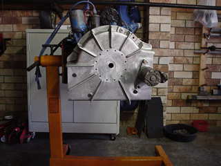
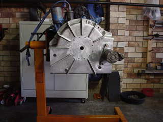
I just got back from my trip and looking at your photo of the mounting
plate, it would appear that the MM positions are similar to the Bellhousing,
but to be sure I will leave that up to Butch to check against his MM
positions.
I will also leave the decision on angled MM up to him also as I'm unsure as
to how this effects everything. However I do understand your comments in
regard to both of these issues.

Butch,
One thing I though of during the last week was a casting problem  concerning
the very tight corners of the bottom LH &RH outer stiffeners.
You might have noticed that I turned one of my top and two of my bottom
stiffereners to avoid these tight corners (no it wasn't for aesthetics).
The problem is getting the sand IN and Out again and if the corner is tight
and sharp, it will invariably lead to poor casting finish in these areas.
Of course if we could see a potential for cost recovery through injection
casting (down the track) this wouldn't be a problem, but as we have to go
through the process of pattern making and testing - we need to look at those
areas before we attempt a pattern.
My gut feeling is that it would look better and wouldn't compromise any
strength BUT the area is tight (limited) around those mounting bolts.

BTW Butch what have you come-up with in regard to the mounting bolt 'in the
centre of the starter'.

And I didn't quite understand the drawing involving the 6 O'clock starter
position.
George (down under)
The AirCraft Rotary Engine NewsLetter.  Powered by Linux.
ACRE NL web site. http://home.earthlink.net/~rotaryeng/
Copyright 1998-2003 All world wide rights reserved.