Butch,
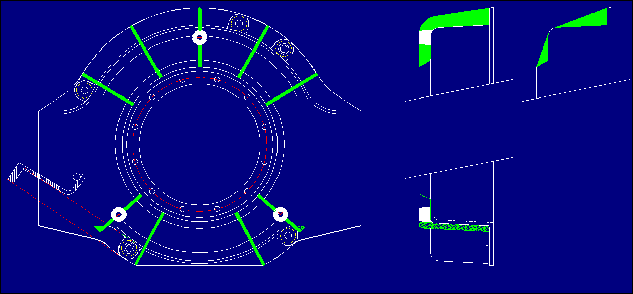
One thing I though of during the last week was a casting problem  concerning
the very tight corners of the bottom LH &RH outer stiffeners.
You might have noticed that I turned one of my top and two of my bottom
stiffners to avoid these tight corners (no it wasn't for aesthetics).
The problem is getting the sand IN and Out again and if the corner is tight
and sharp, it will invariably lead to poor casting finish in these areas.
Of course if we could see a potential for cost recovery through injection
casting (down the track) this wouldn't be a problem, but as we have to go
through the process of pattern making and testing - we need to look at those
areas before we attempt a pattern.
My gut feeling is that it would look better and wouldn't compromise any
strength BUT the area is tight (limited) around those mounting bolts.
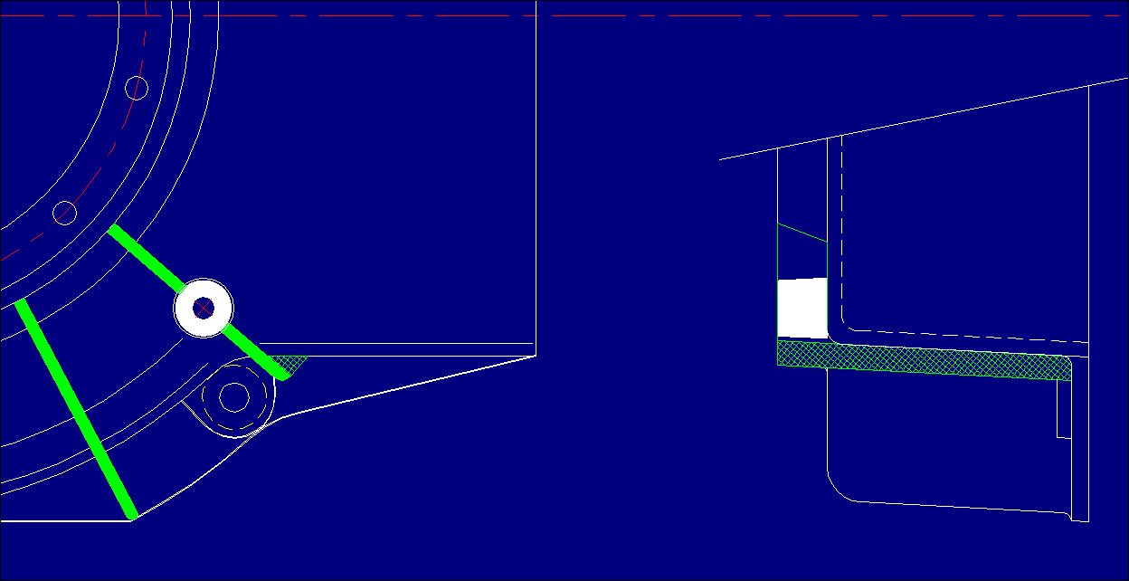
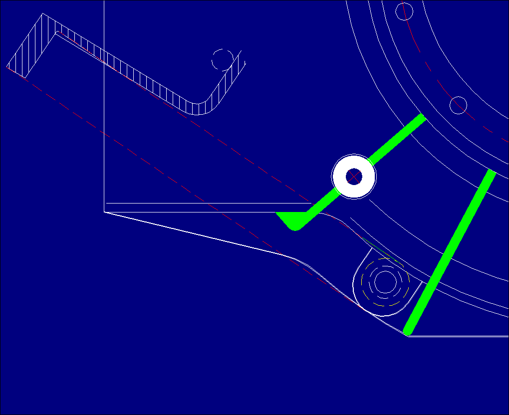
******You're absolutely right on that one George, any acute angle under 45
degrees should be avoided on sand Castings, unless the surfaces are going to
be machined finished......So, I went back to the drawing board (2 times) and
this is the best of both results.....I reworked the cross sectional area and
shifted it tighter in so as to transfer column/compressive loads directly to
the face of the 13B, ran a quick check and it came up pretty good, and
certainly Sand Packing Friendly :) ....The bolt Pad can be blended right up
against the Fin at your discretion, same goes for the other 2 on the L/H side.
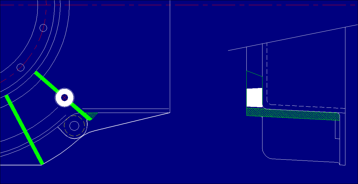
All 5 Flange mounting hole Pads must be faced to remove side to flange fillet
radiuses, and provide a parallel surface to the rear of the Flange, with a
22mm (.875") C'bore, with a 1mm (.040") radius ground on for prevention of
stress concentration. This will provide ample clearance for a 14mm socket and
10mm Flange Bolt combo.

The odd-ball 8:30 mounting hole, the one that's closest to the center of the
e-shaft will be the only one impacted by the counterboring operation as it
will be cutting into the Bellhousing's side wall to a max depth of 1.8mm
(.071"). This is quite acceptable as it's well bellow 50% of the wall
thickness so an internal bulge is not required.....(See attachment -3)
BTW Butch what have you come-up with in regard to the mounting bolt 'in the
centre of the starter'.
******George, will be putting that one to sleep once and for all, next.
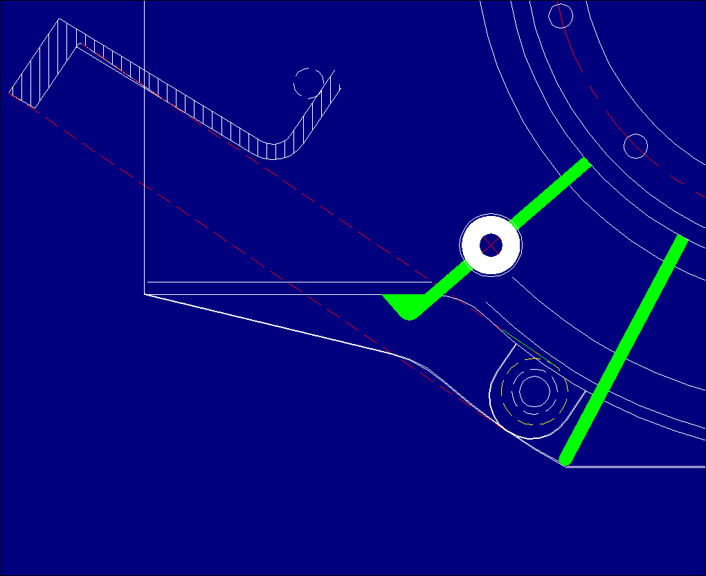
And I didn't quite understand the drawing involving the 6 O'clock starter
position.
George (down under)
******Don't panic Georgie, those are just construction lines just to see if
it's do-able.......My mussings so far: ....It is very DO-ABLE and I will be
tackling it very, very soon....I've been toying with an idea in my head???

Butch
Butch send me some drawings in dwg format. I want to check this stuff in 3D.

Paul Lamar

The AirCraft Rotary Engine NewsLetter.  Powered by Linux.
ACRE NL web site. http://home.earthlink.net/~rotaryeng/
Copyright 1998-2003 All world wide rights reserved.