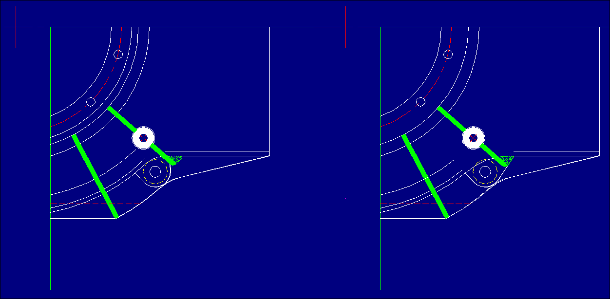
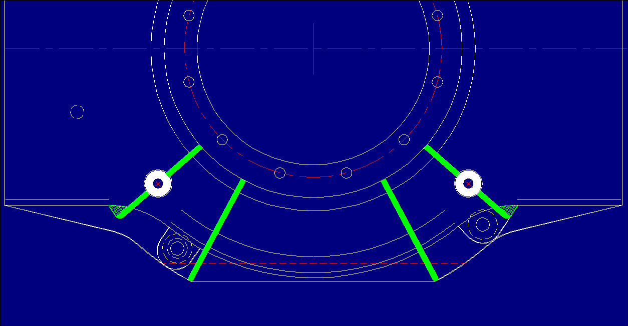
All 5 Flange mounting hole Pads must be faced to remove side to flange
fillet radiuses, and provide a parallel surface to the rear of the
Flange, with a 22mm (.875") C'bore, with a 1mm (.040") radius ground on
for the prevention of stress concentration.
## Understood, however I kina felt that the corner radius was needed to
avoid stress concentrations, I haven't seen any machining on car
bellhousings so is this a little overkill ?-OR does the fact the
commercial bellhousings being  injection cast have that much better
finish ?
******George, the number 1 choice is not to remove the fillet radius at all
to begin with, BUT when you HAVE TO, as in our application, all possible
precautions should be taken into consideration hence, cut the largest RADIUS
you can possibly fit in, an .040 to .060 RADIUS ground on the c'bore/end mill
is the max size for us. FYI, this radius actually serves as a bridge to
prevent stresses from gathering and having a party in the corners and wreak
havoc.....This is general common practice especially in the Aerospace and
Nuclear Industry.
The odd-ball 8:30 mounting hole, the one that's closest to the center of
the e-shaft will be the only one impacted by the counterboring operation
as it will be cutting into the Bellhousing's side wall to a max depth of
1.8mm (.071"). This is quite acceptable as it's well bellow 50% of the
wall thickness so an internal bulge is not required..(See attachment -3)
##If it's OK with you I may decide to put a little one in, for piece of
mind

******It's okay with me, there's nothing wrong with belts & suspenders in
this area.....You now have 2 PLACES....Just keep reading Georgie.
Butch send me some drawings in dwg format. I want to check this stuff in
3D.

Paul Lamar
******NTW Paul, just as soon as I've cleaned-up a few Cats & Dogs, I'll be
sending a .dwg, very soon......Just hang in there bored to death, since you
have nothing else to do :-)
Butch- In conclusion, well I guess  that modification of yours has been
tested by your programme, but for the life of me I never would have
thought of that, nor can I understand how it could be as strong -I  just
don't have the training.
What I could do is turn that flange a little bit out at the bottom and
blend it all in nicely
That's the difference between you having the training and me trying to
guess. Finally I won't have any problem with these corners- not at all !!
******No program necessary George, just a simple rule....A straight member is
stronger than a bent one when subjected to point loading, generally any part
of the member past the bend is worthless and adds nothing but weight to the
application.....So again, I'll have to explain this over a glass of "Red"
sometime.....(These glasses are turning into bottles) :)
Hey! didn't you like my bent stiffeners?
George
******Of course I liked it, and it was appropriate for the SQUARE corner as
it was pretty far from the Engine Flange (Hanging out in space).....Now, with
the ROUND Flange it's a totally different game!!

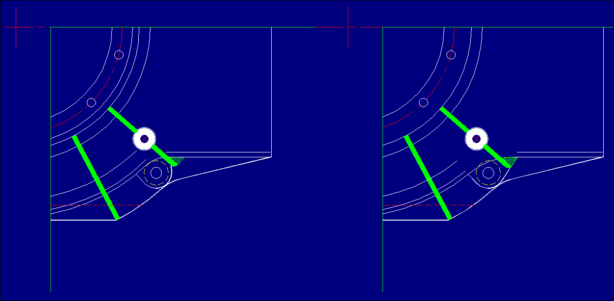
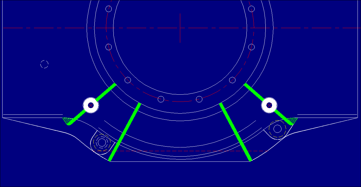
******Georgie the attachment is going to put a great big SMILE in your face.
I made a couple of add'l changes in this area that was bothering me and you
too.....I changed the Armpit radius by the 2 bottom Flange mounting bolts in
question, from 25mm (.985") to 60mm (2.36") Radius, this will require 2
internal Bulges now.

Butch
The AirCraft Rotary Engine NewsLetter.  Powered by Linux.
ACRE NL web site. http://home.earthlink.net/~rotaryeng/
Copyright 1998-2003 All world wide rights reserved.