I am just getting around to wiring Tracy EFI/IGN computer
and I had an idea. Tracy uses a 37 pin D sub min male connector
that is rather hard to attach tiny wires to unless you are real
good with
a tiny soldering iron or you have a special crimping tool.
This is a job I was not looking forward too as my eyesight
and hand coordination is not what it was when I was younger.

I was driving home from the hangar tonight and had an idea.
I have a whole bunch of these terminal strips left
over from another project and I had the idea of making a small
printed circuit board that would adapt a male 37 pin D sub min
printed circuit board connector to these easy to use terminal
strips.
Merely strip the wire, insert it in the hole and tighten the
screw.
I am laying out the PC board and will order a bunch of mating male
37 pin D sub min connectors to solder to the printed circuit
adapter
board. If anybody wants such an adapter let me
know. Cost should be around $20 or $30.

Paul Lamar
After reviewing the installation instructions on the EC2 it looks
like it might be better to have 15 pin D sub min on the printed
circuit
board as well to connect to Tracy Programming & Control Module. PCM
for short.
15 fewer terminal blocks would then be required.

Pins 5,6,10,14,15,16,24,25,26 and 32 all go to the PCM. In that case
a 15 wire, off the shelf molded cable with 15 pin D sub min
connectors
could be used to connect to the PCM located on the instrument panel.

This would further simplify the wiring and speed the installation.
I'll work on the 3D for that.

Tracy, will this idea also work on the latest EFI/IGN system and the
EM2?
Paul Lamar
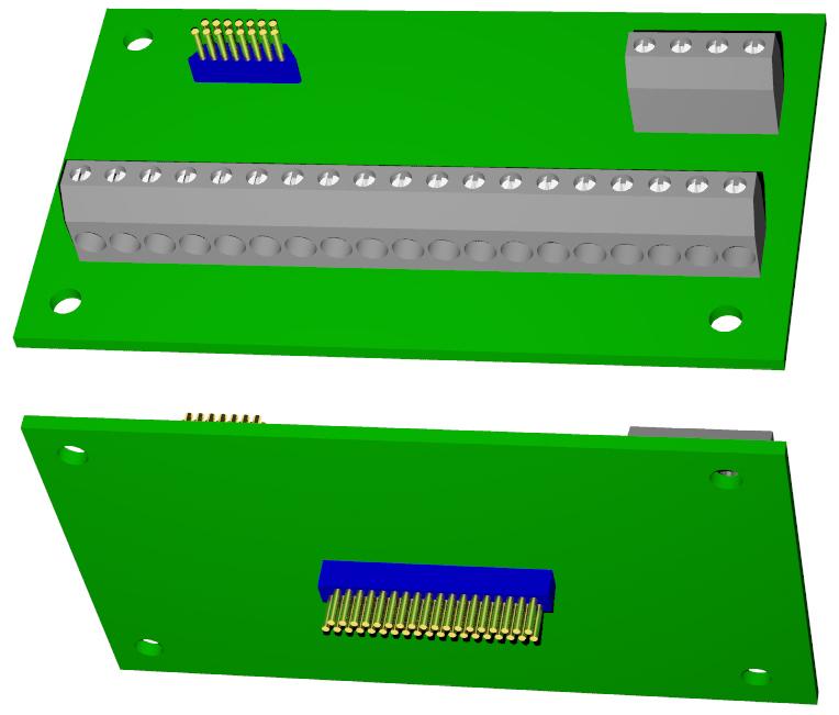
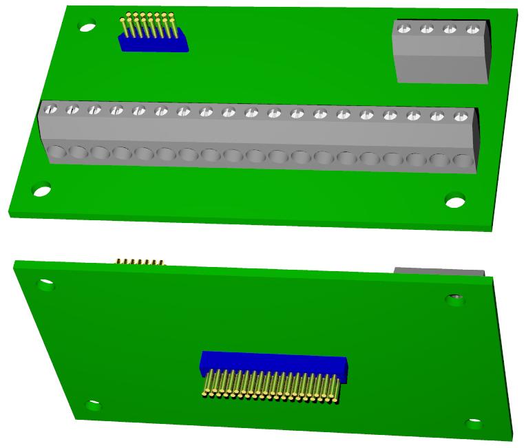
Here is what it would look like roughly.

Paul Lamar
Paul, see my other e-mail for the url to Phoenix Contact. They have
exactly what you need. you can get the terminal blocks with the
terminals
front or back. Bill Jepson
But Bill how would they know what pin assignment Tracy made from the
37 pin to the 15 pin? That is one of the key features.
Pins 5,6,10,14,15,16,24,25,26 and 32 all go to the PCM. In that case
a 15 wire, off the shelf molded cable with 15 pin D sub min connectors
could be used to connect to the PCM located on the instrument panel.
These wires go to specific pins on the 15 pin D sub min connector on the
back
of the PCM.


That is a huge site Bill I can't find anything on there that remotely
solves this problem. Perhaps you could capture the picture of the device
and send it to me.

Paul Lamar
Mike Perry wrote:
Paul,

Look at www.phoenixcon.com/subcon .  I found this in one of my trade
publications and was thinking of replacing the original 37 pin connection I
got with my EC2.

When I first wired my EC2 I was having a problem with the injectors not
functioning correctly.  I even sent the EC2 back to Tracy to check.  EC2
checked out fine.  When I did a pin by pin continuity check everything
appeared fine.  After a month and a half retracing every wire and connection
I had one of the wires on the 37 pin connection come off in my hand while I
was tracing wires.  One of my solder joints was bad on one of the injector
pins.  The connection was good enough to show zero ohms but not good enough
to carry the current required.  I now have a little over 4 hours of running
time on the engine.

Mike Perry
Long-Ez, 13B--
I hope to make the process of connecting it up easier and more reliable.
It is kind of tricky working with tiny 22 to 24  gage wire and D sub min pin
sockets. You need excellent eye sight and maybe a microscope :)
We need to get the process up to the miniature size :)

Here is the latest proposed idea. The 15 pin D sub min goes to the PCM.

Here too is Tracy wiring list for those few people who don't yet have
Tracy's excellent EFI/IGN system. Note how the D37 sub min pins are mixed and matched
with the signal lines going to the 15 pin D sub min connector on the back of the PCM.


Paul Lamar


The AirCraft Rotary Engine NewsLetter.  Powered by Linux.
ACRE NL web site. http://home.earthlink.net/~rotaryeng/
Copyright 1998-2003 All world wide rights reserved.
EC2 Engine Controller Terminal Assignments and Destinations	01 -24-00
		TERMINAL		DESTINATION
	I.	Ground connection		Ground stud on EC2
	2.	N/C		No connection
	3.	Trailing coil ignition control		Red wire on Mazda trailing coil assembly
	4.	Crank Angle Sensor (CAS) 2		Red wire on Mazda Crank Angle Sensor (CAS)
	5.	Mode Select switch 0		Pin 11 on the Programming & Control Module (PCM) connector
	6.	Mode Select switch I		Pin 3 on PCM connector
	7.	Serial Data out		Future connection to fuel flow instrument
	S.	JC		No connection
	9.	N/C		No connection
	10.	Mode Select switch 2		Pin 10 on PCM connector
	II.	Temperature sensor power (Vcc)		Temp sensor wire (either)
	12.	Disable leading coil	t	Top pole on Coil Test switch
	13.	Disable trailing coil	t	Bottom pole on Coil Test switch
	14.	Control panel power (Vcc3)		Pin 7 on PCM connector
	15.	AIB (Controller) Select switch		Pin 5 on PCM connector
	16.	Ground		Pin I on PCM connector
	17.	Rotor I primary injector	*	Rotor I primary injector (center port on rotor 1)
	IS.	Rotor I secondary injector	*	Rotor I secondary injector (outside port on rotor 1)
	19.	Injector return	*	Ground on airframe near battery terminal
				(See section on ?Fuel Injector Wiring?)
	20.	Trailinc coil select		White wire on Mazda trailing coil assembly
	21.	Leading coil ignition control		Red wire on Mazda leading coil module
	22.	Crank Angle Sensor (CAS) return	#	White wire and white with black stripe wire on CAS
	23.	Crank Angle Sensor (CAS) sensor I		Green wire on Mazda Crank Angle Sensor
	24.	Mode Select switch 3		Pin 4 on PCM connector
	25.	Program voltage		Pin 9 on PCM connector
	26.	Mixture Control voltage		Pin 15 on PCM connector
	27.	N/C		No connection
	25.	Future connection to fuel flow instrument (02 sensor) Install wire but do not connect at this time (insulate wire)
	29.	Tachometer output (12 pulses / rev. 12 volt pulse)		To fuel flow instrument or Engine Information System (ELS)
	30.	Cold Start switch		Pin 13 on PCM connector (And injector disable switches if used)
	3 1.	Inlet air temperature sensor		Air temperature sensor (either wire)
	3~	Program Store switch		Pin 2 on PCM connector
	33.	Controller power (+12 volts)		To controller power switch
	34.	Controller power (+12 volts)		To controller power switch
	35.	Rotor 2 secondary injector	*	Rotor 2 secondary injector (outside port on rotor 2)
	36.	Rotor 2 primary injector	*	Rotor 2 primary injector (inside port on rotor 2)
	37.	Injector return	*	Ground on airframe near battery terminal
				(See section on ?Fuel Injector Wiring?)

*	Indicates connection to be wired with 20-gauge wire. Make all other connections using 22-gauge wire. Twenty (20) gauge
wire needs to be used for these six specific connections; however, do not use 20 gauge wire for all connections or the back shell
will not fit on the harness connector.

t	The center (common) connection of the SPDT Coil Test switch is a ground connection. Connect it to a 22-gauge wire and
terminate it with a circle lug connected to the grounding stud on the EC2 case. The shield for the crank angle sensor
(CAS) wires should also be grounded here.

# Do not attempt to solder two wires directly to the connector. Splice the two return lines of the CAS together near the CAS
and connect them to the EC2 with a single wire. Note that the wires between the CAS and EC2 should be shielded.