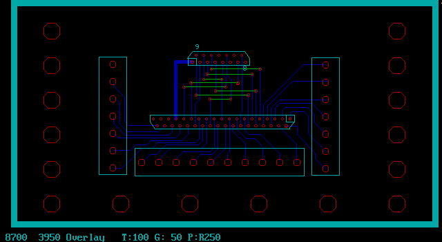
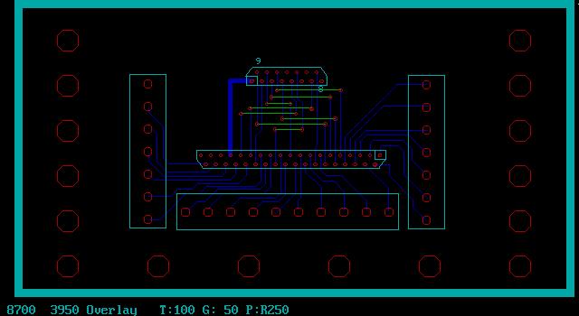
Here is a first cut on the PC board.
The large holes are for tie wrapping the wires to the PC board
for strain relief.

As far as terminal blocks are concerned they are functionally
equivalent to a crimp connector which are preferred by NASA
over solder connections. You just need to make sure the screw does
not loosen. A drop of hard wax or RTV ought to do the trick.
Loc Tight screw lock will also work.

BTW a subtle advantage of this approach is a wire size can be used
that will match the wire size Mazda used for all of their engine
connections. 22 to 24 gage wire typically found in D sub min terminated
cables is a bit on the small side for automotive wiring harnesses.
It is not that it won't carry the low currents involved it is
just a little harder to work with when connecting to automotive
connectors used on the ignition modules and the fuel injectors.

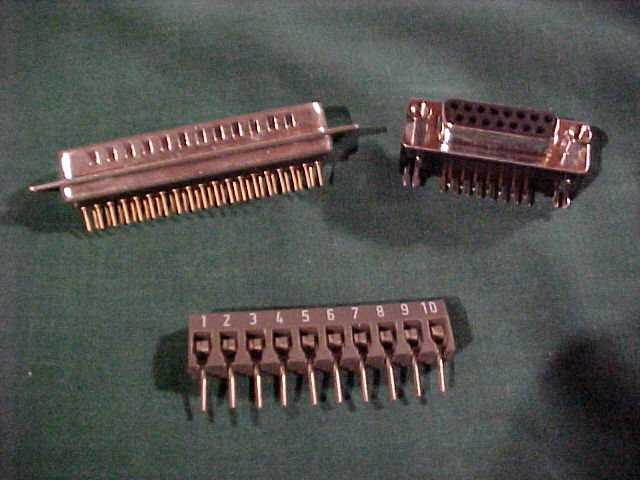
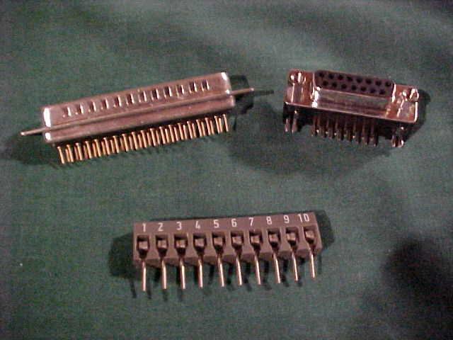
There is also a picture of the connectors used. The 15 pin right
angle allows an off the shelf 15 wire cable to connect to Tracy's PCM
module. There will be three of the ten contact terminal blocks.

The layout shows only one ten terminal using and two eight's
but I ran out of pins so I will use three tens.

The 37 pin male connector on the top left plugs into Tracy's
37 pin female connector on the top of his box.

Paul Lamar

The AirCraft Rotary Engine NewsLetter.  Powered by Linux.
ACRE NL web site. http://home.earthlink.net/~rotaryeng/
Copyright 1998-2003 All world wide rights reserved.