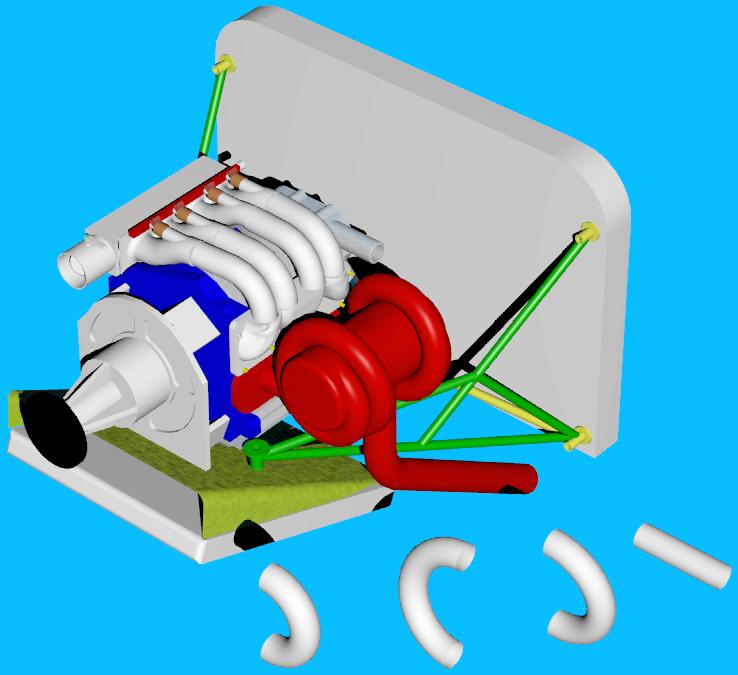
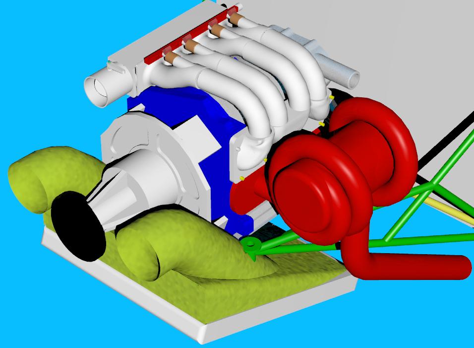
The yellow parts are left over Van's parts. The rest of Van's
motor mount is cut away and discarded. The green diagonal tubes
going down to the nose gear leg socket take most of the download from
the engine and feed it directly into the landing gear.
The rear motor mount could be a compression  strut with rubber ball joints
down to the same point. Not shown.

The type of front motor mount brackets are not shown and could be
a motor plate or a Schertz beam. Starter is not shown.

The rad shown is 24 inches long by 20 inches wide and 2 inches thick.
A Kays and London simple oblique diffuser is used. Rad air is exited
out the bottom of the cowl with louver flaps.

The monster tuned tang. muffler with 32 inch long 2 inch diameter
tubes is about as large a muffler as can be fitted under the cowl.
The center line radius of the two 180 degree bends that make up the
tube spirals is five inches. The center can is eight inches in diameter.

The muffler is about 12 inches long. A 2.5 to 2.75 diameter down
pipe can go out the side of the cowl or down and out the bottom
>from the center of the can. Not shown. The trick to welding this
muffler is weld the can ends on last.

A smaller six inch can would cut the size of course. In that case a
four inch center line radius would be used for the 180 degree bends.

A simple tang muffler, a VAM or large turbo would fit easily.

This motor mount may need a couple of more tubes. I am still thinking
about it. Perhaps one tying the two front mounts together
under the engine.

BTW I need the dimension from the firewall to the prop flange
for an RV8a or RV6a cowl. Anybody have that dimension?

Paul Lamar
Excellent design! In a few years when the Rotary is certified, and
Lycosaurs are extinct, Vans will finally be forced to manufacture and
sell this engine mount.

--
Perry Mick
http://www.ductedfan.com
Thanks Perry. If you plan carefully there is almost enough room in there
for two rotaries :)

Paul Lamar
Here it is with a more reasonable sized tuned tang muffler. Namely a six inch
can. The parts in front are the 180 degree tubing bends used to make the
muffler parts.

The second illustration is an idea I had to reduce the cowl work.
I hate fiberglass.  It might work. I am not sure. Normally a
scoop would be formed just below the spinner.

Just dumping the air in and letting it find it's way through the
rad past the engine is not a good idea. Every degree increase in air
temp reduces the cooling roughly 1%. The ducts shown are five inches
in diameter.


Paul Lamar

The AirCraft Rotary Engine NewsLetter.  Powered by Linux.
ACRE NL web site. http://home.earthlink.net/~rotaryeng/
Copyright 1998-2003 All world wide rights reserved.