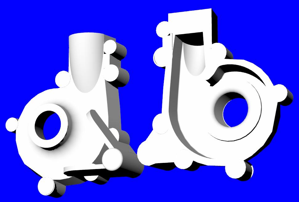
This is what UG is capable of. Multiple intersecting conic
     surfaces
     > and blends. The surfacing in this part would be a
     challenge even in Rhino.
     > The detail in the sculpted parting line impossible in
     most mid range solid
     > modeling packages. AutoCAD..ha. good luck. UG is a
     powerful package I hate
     > to give it up but oh well. The only thing that comes
     close is maybe Catia

UGH, Monty, I think you could do this part in Rhino OR SolidWorks.
I have used most of the major cad packages SDRC Ideas, PE, and
Catia and I believe Catia is the worst of all of them. When it comes
right down to it it depends on what you want to do, AND how you
learned to do it. This is like the priming arguement on alclad
aluminum planes. You ask 5 people you get 5 different answers.
SolidWorks is getting better, though the GUI is NOT as good as
Rhino, or Anvil just to name a couple.
 Group if you want a good price on a PC based cad system you
need to be on the lookout for the occational specials, and ready to
buy when they happen. I recently bought the newest SolidWorks
(I need interconnectability) Office for 3k out the door. This
includes
a limited fea package. Rhino can be had for less, and I believe I
would use it if I wasn't doing drawings for sombody else.
Bill Jepson
Bill,

I too have used many of the major Cad packages. I hate the interface on
Catia as well. PE is too restrictive in the way you have to model parts. We
joke about it all the time. "hey did you make that in PRO-E?"  Kind of an
insult. Anyway I have also trained a lot of people transitioning from other
packages. I hear a lot of things like "wow! that's all you have to do?" or
"man, that would have been impossible in X" Pro E is fine if all you are
doing is the usual mechanical design tasks. For freeform surfacing it just
doesn't cut the mustard. They used to send their whizz kid in to try to get
us to switch to Pro over UG, We would get all the designers around and give
him tasks. We would have that thing locked up and crashed in 5 min. Poor
kid. The whole sketch based system is too restrictive (you can use sketches
in UG if so inclined). Plus trying to make every little curve tied to a
sketch and interdependent makes the thing cumbersome and prone to blow up
when you make a change. Working in UG is a lot like Rhino except that it is
parametric. Don't get me wrong, I love Rhino. It just won't do anything over
rudimentary solids.

Solid Edge and Solid Works both work on the Parasolid kernel. This is what
UG uses and it where it came from. Where the mid range modelers fall apart
is on blending complex shapes, and the ability to do conic blends. They also
usually have limited surfacing capabilities. A lot of the tool makers I have
worked with use Solid Works and it is a good package. There are however,
some things that it just can't do and I usually wind up making surfaces for
them so they can construct tooling.

Rhino has truly first class surfacing. Unfortunately it falls apart when you
try to add fine detail in solids. Or attempt to make blends around complex
intersections. Sure you could make both an inner and outer shell and sew
them together. Then you could construct the blends manually. Then you have
to try to get it to be a watertight solid. It would take you months to do
what can be done in a day in UG. Where UG shines is in the fact that it
combines parametric modeling with powerful surfacing, the ability to model
it in solids, and powerful assembly tools. This has made it the standard in
plastics, automotive, and aerospace industries.

What you can't see in that picture is the detail on the parting line. There
is an O ring seal groove around the whole part. There is also a styling
groove and interface rib that goes all the way around the perimeter. The
back is also curved in the Z direction, yielding a non planer parting line.
Trust me. It would be very difficult to do in a mid range package. Virtually
impossible in Rhino.

That said the mid level stuff is catching up and it looks like Solid Works
is the way to go. Make the outer surface Rhino, import and trim in SW. All
for a lot less than $25K. It is more trouble though. No free lunch.

For the people on this board I would definitely say Rhino will do almost
anything you want it to and then some.

Is the solid works deal still on?
Monty
"Or attempt to make blends around complex
intersections. Sure you could make both an inner and outer shell and sew
them together. Then you could construct the blends manually. Then you have
to try to get it to be a watertight solid. It would take you months to do
what can be done in a day in UG."
It is not as hard as you think Monty. I have solved most of those
problems.
It took me a while to catch on.  I had to or they would not work in
the stereo lithography machine. A lot depends on the order in which
you do things.
The books don't tell you that. That took me awhile to figure out.  One
of the tricks is to scale the part down and "difference" it from the
real part to form a shell. You scale the different axis's at different
rates.
I got so I go do these things in a few hours.

Here are some complete solids in Rhino. All my castings had to be
complete
solids or they would not work in the SLM. It would be nice if there
were
a shell command in Rhino like found in Solid Works.

Also the people at Rhino told me they have made improvements
for some of  those problems in the later versions. I have been so busy
upgrading my NC mill lately I have not got around to upgrading.
I am still using version 2. There is no doubt in my mind with a little
more development on Rhino's part that it will do what solid works does
eventually and with a much better and easier to learn user interface.


Paul Lamar

The AirCraft Rotary Engine NewsLetter.  Powered by Linux.
ACRE NL web site. http://home.earthlink.net/~rotaryeng/
Copyright 1998-2003 All world wide rights reserved.