The key word "ejector" seems to be the hot tip.
I have not read all these yet so if you find one you like let me know.

http://naca.larc.nasa.gov/

I do have Report 818 and that is a good one. Very comprehensive.

Here is a summary.

Paul Lamar

**********************************************************
2259. Manganiello, Eugene J Bogatsky, Donald , ***An experimental
      investigation of rectangular exhaust-gas ejectors applicable for
      engine cooling ,
         <http://naca.larc.nasa.gov/reports/1945/naca-report-818/>* NACA
        Report 818 , 1945 , pp. 19 .
*********************************************************************

According to Report 818 these are the configurations that worked best.
With a 24 inch long Straight section and 12 inches long Diffuser section
they got as much as 6 inches of water pressure drop. The lengths
are rather important. If you make them shorter you don't get as much
pressure drop. 6 or 7 inches gets you about 4 inches H2O of pressure drop
if I read this correctly. The divided version did not work as well
as the non divided version. Something like this is used on a Cessna 210
as I recall.

Note the fish tail nozzle. Probably you would not need a muffler.

The question is what can you make them out of that will be light weight?
The Cessna 210 used SS as I recall. Carbon fiber might work for some of
the parts. Brazed SS honeycomb panels about 1/4 inch thick would be ideal.

The length required suggest mounting them under the engine. That does not leave
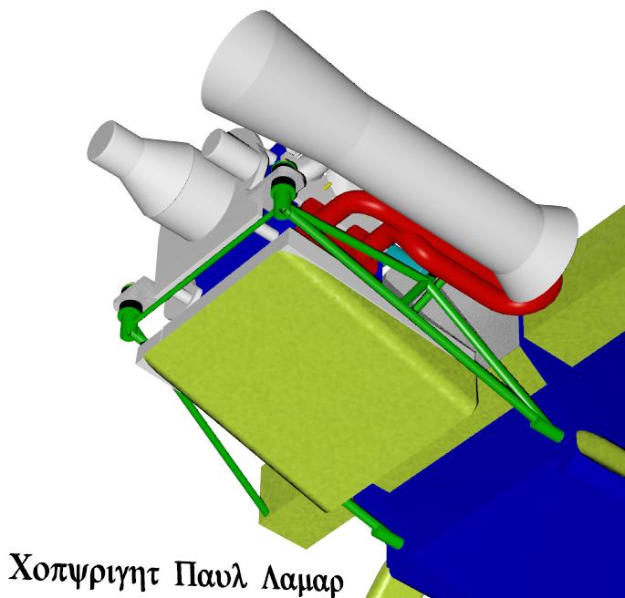
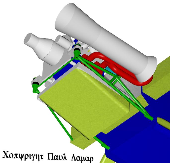
much room for the radiator.  Here are some scale 3D's I did for Joe Berki awhile
back. They could stand a bit of refinements based on Report 818. A longer
ejector is called for. Also a beam type motor mount would give a bit more
room for routing the exhaust pipes. Also where is it written that the ejector
needs to be on the center line. An asymmetric location may work better
in conjunction with a long narrower radiator. That is rather intriguing to
me.

Note the cut away lower fuselage with the lower motor mount bolts
sharing the landing gear pivot bolts. That is a lighter, stronger
way of doing it and it yields more room for the rad ducts.

Ah the heck with it just use a P51 ram air scoop :)

Paul Lamar
According to Report 818 this should be good for about six inches of
H2O as long as the entire cowl is well sealed. The air finds its way
through the rad up around the oil pan and forward into the ejector
opening. One problem I can see is the oil pan might develop a little
positive dynamic pressure cutting the rad air flow a bit.
The ejector is hiding behind the spar but a top and bottom fairing
will be required to blend it in with the rest of the cowl.

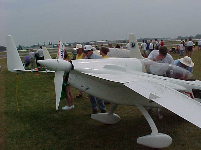
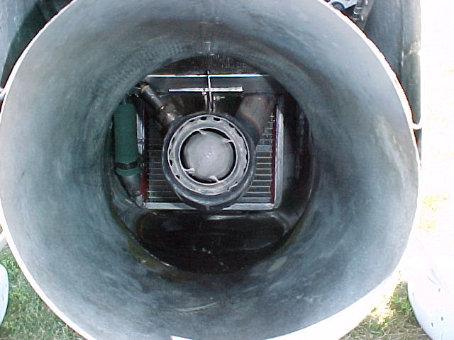
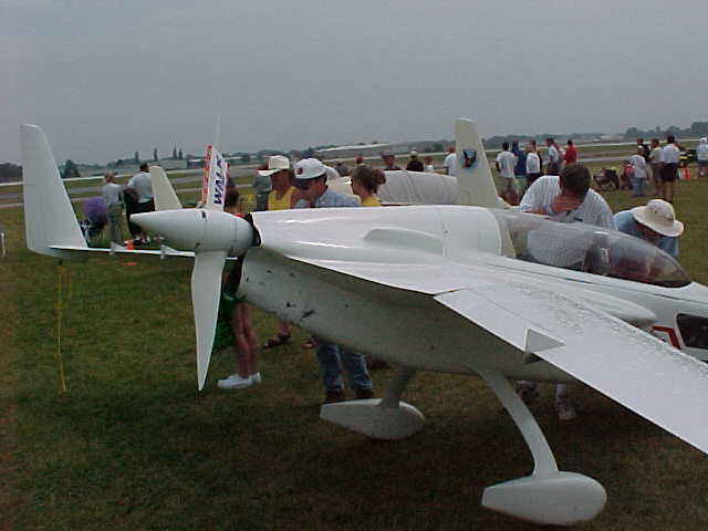
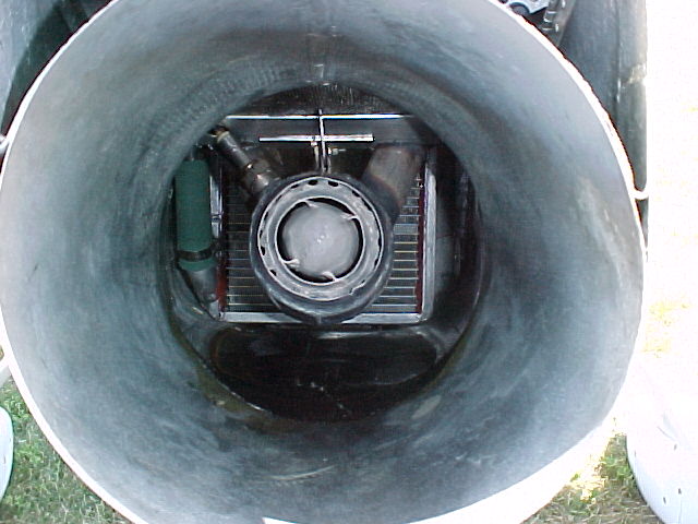
BTW here are some pictures of Charlie Airesman's ejector set up as well.
The long ejector tube is under the engine.

Paul Lamar

The AirCraft Rotary Engine NewsLetter.  Powered by Linux.
ACRE NL web site. http://home.earthlink.net/~rotaryeng/
Copyright 1998-2003 All world wide rights reserved.