Eric Ruttan wrote:
Is it correct that a Shertz Beam is developed enough to produce a
finished
product?  For a pusher canard install?

If I am behind and there are suppliers, or someone might be
interested, then
please post details here, or post a link to details, or post the
details to
http://tinyurl.com/2aves

The url leads to a web site that has many members interested in pusher
installs of rotary engines.

Thank you
Eric.
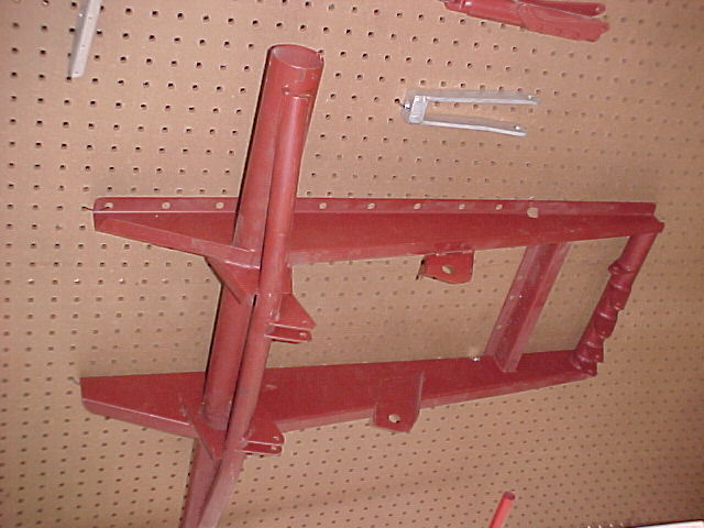
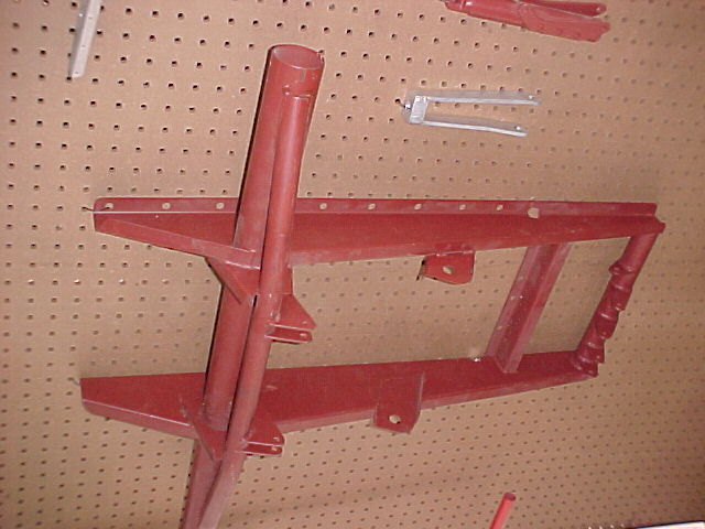
The Schertz beam is more or less a concept rather than a specific
device.
It refers to a simple beam under the fly wheel iron end housing end of
the engine.
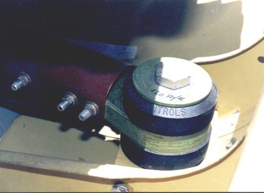
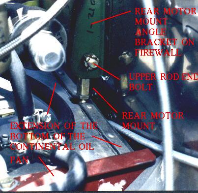
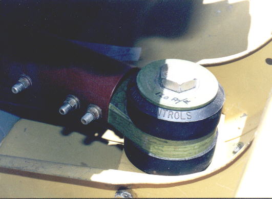
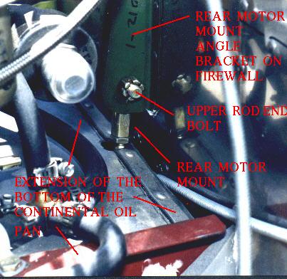
The beam is located under the oil pan flange rather than between the
oil pan flange and the engine. It uses low cost Barry Controls
industrial
rubber bushings as motor mounts. Very similar to a Questair Venture
motor mount.

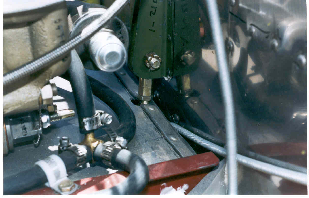
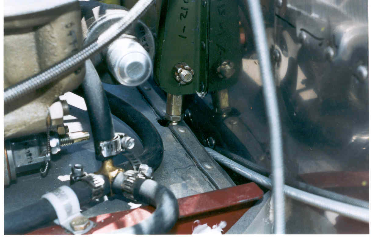
Here are two examples.

Paul Lamar
Alex Madsen wrote:
As a (soon to be) Mechanical Engineer I can say I do not like the looks
of the Shertz Beam. While I have done no structural or dynamic
calculations this design, I see a fundamental flaw in it. The engine is
only supported at 2 points. This means that it is not well constrained
(well) in the rotational axis about the beam. There are 2 problems with
this. One is possible rotational resonance (possibly leading to damage).
The second is a large acceleration in the forward or aft direction will
cause a tremendous moment (torque) on the 2 mounting points. Lets for
the sake of argument say the engine is 250lb and its CG 1.5 ft above the
beam. If it experiences a 10 g acceleration it there will be a 3,750
ft-lb moment on the mounting points. G lodging gets a lot higher that
that in "emergency situations" and I would hate to have my engine come
flying through the firewall.

F*G*L=M so 250lb*10g*1.5ft=3,750 ft-lb

PS If someone shows me that the numbers for a Shertz Beam are ok then I
would consider using one.

And yes I know I can't spell.
All good engineers cannot spell. That is what speeling checkers are for.

You are absolutely right except for a couple of points. First and foremost
you are missing the third motor mount :)

You also won't see ten G's fore and aft unless you crash into a brick wall :)
You will see six vertical G's in hard landing and since the Schertz beam is
located at or about the engine/PSRU/prop combination CG there will be little
or no moment about the beam axis. The beam is designed for six G vertical load.

There is a moment due to prop thrust... say six inches times 800 pounds or 4800 inch
pounds. The rear mount is about 18 inches aft of the beam
so that is an upload on the rear mount of 270 pounds. That can be partially
off set by moving the beam slightly forward of the engine/PSRU/prop combination
CG causing a download on the rear mount.

BTW All Questair Venture's have been flying for years with this type of motor
mount using TIO-550's with top speeds over 300 MPH. Here are some pictures.

I will leave the calculation of the moment of inertia and the stress on the
hat section to the student :)

Paul Lamar

The AirCraft Rotary Engine NewsLetter.  Powered by Linux.
ACRE NL web site. http://home.earthlink.net/~rotaryeng/
Copyright 1998-2003 All world wide rights reserved.