MRE-FB wrote:
Hi Paul,

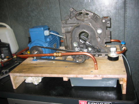
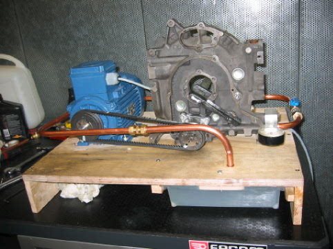
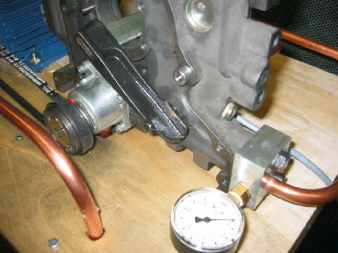
As promised, here are some pictures of the oil pump test rig.  We create
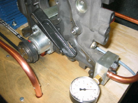
back pressure by progressively closing the valve on the right hand side.
We measure pressure with a 0-10bar pressure gauge, just out of the iron.
We measure flow with an ultrasound digital flowmeter (not installed when
these pics were taken), and we measure RPM on the pump pulley with a
stroboscope.

We tested both the '89-'92 13B single-turbo pump and the '93-'95
twin-turbo pump.  The one you see on the rig is the latter one.  We feed
it oil two ways:  through the regular pickup tube attached to the bottom
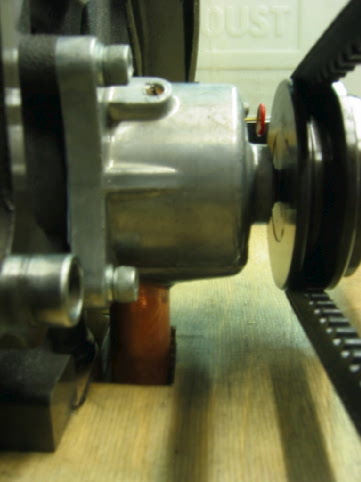
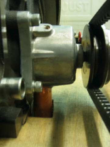
of the iron (not visible on the picture) and through a SECOND PICKUP
TUBE (the copper one visible on the picture) inserted in a 5/8'' hole
drilled through the side of the pump body and feeding the oil to the
side passageway Mazda put in its later model pumps.

Best regards,
Francois Badoux
OK I get it now. Good idea to use a front end housing. We got those
lying around too. Is that a synchronous electric motor there? RPM?

If I were doing it I would add a valve in the outlet pipe to
simulate the oil pressure drop across the block.

Paul Lamar

The AirCraft Rotary Engine NewsLetter.  Powered by Linux.
ACRE NL web site. http://home.earthlink.net/~rotaryeng/
Copyright 1998-2003 All world wide rights reserved.