Lynn,

 Thanks Mate!!
 I was hoping for something easier, but I've got to sort this out as it is
 bugging me and the timing has always been a mystery to me.

 So when I get to this stage, what are we looking for?
 Do I have to put in the rotor to see that the side seals are doing or do I
 work off the apex seal location.

 Excuse the ignorance here mate - I am at a complete loss with all this stuff
 on timing.

 If you have any good stuff on timing (other than what we have), feel free to
 send it to me direct lendich@hypermax.net.au  I need all I can get.
 George (down under)
The first interest will be to determine if TDC on the front pulley is really
where it should be. Or in some cases there isn't one. So you find TDC on the
big degree wheel, and leave the rig sitting at TDC, and bolt on the front cover
with two bolts and slip on the front pulley with the key and the big bolt.
Just finger tight is fine.

There are two studs in line, one above the other holding on the water pump
housing. The upper most stud is just a bit closer to the plug side of the
engine. Sight along the plug side of the upper most stud, (not the nut) through the
center of the little piece of wire used for a pointer to the TDC groove in the
pulley if any. If no mark exists for TDC, mark the pulley and file a groove
and fill with paint.

Should the groove in the pulley not be in line as in above, but is close,
move your head a bit so as to line up the wire pointer and the groove, if this is
possible. If, by moving your head a bit (off of the sight line of the upper
stud) and make the wire line up centered in the groove, make a white line on
the pump housing to use as a new sight line reference just for this engine
assembly, instead of the stud.

Once you have a very accurate TDC mark and can push the crank off TDC, try
turning the crank back to TDC by looking only at the TDC mark on the front
pulley and your sight line. Turn it back to where you think it is dead on, and then
look at the dial indicator to see if you are correct. In not too long, you
can get to with one degree of TDC by just looking at the stock pointer. Once you
can do this repeatedly, you can go to the next step below, if it is helpful
for you.

If you don't have any structure above the land area where the old top mount
starter would have been, you can make up a big easy to see pointer from sheet
stock and do the above but paint a starter ring tooth white for TDC, and mark
one red for 20 degrees before TDC for ignition timing (or whatever you want).

Just stack up the rest of the engine parts with only the stationary gears the
iron and aluminum housings and dowels, but no rotors. Mount the flex plate or
flywheel, or whatever has the starter ring teeth on it. and install the key
in the crank and the big nut, snug but not torqued. With the engine still
sitting at TDC make up your pointer as above and install it. In most cases there
are still two threaded holes where the top starter mounted or two smaller holes
where a dust cover was bolted on. The particular tooth you choose makes no
difference. Mount the pointer pointing at a tooth. Paint that tooth white.

Divide the number of teeth on your flex plate by 360 to get a degrees per
tooth figure.

Turn the crank backwards the number of teeth required to equal 20 degrees
or whatever advance number you want to run, and paint that tooth (or it may
be a valley between teeth), red. Now you can have all kinds of junk blocking
you view of the front pulley, and still put a timing light on the flywheel and
get a very accurate timing reading.

You may have detected by now, that if before you take the big degree wheel
off of the crank to build up the engine stack, you could clamp it to the front
pulley, (without moving the crank) make a temporary pointer from welding wire
and set that pointer at TDC. So long as the crank is not moved between the big
pulley coming off of the back and going on the front, you will have maintained
the TDC relationship.

You could also use the smaller degree wheel clamped to the front pulley to
start with and have the pointer set up as above so the relationship can be
recovered if the crank is moved while installing the flywheel or flex plate. The
pointer on top with the painted flex plate teeth are very easy to see, and
timing checks are a breeze.

So that takes care of the ignition timing, and establishing an accurate TDC.

If you plan to alter the porting on your engine or just record what you have
now, just return to the TDC setup with only the front plate. Move the crank
and pointer to the TDC (Firing) position as before. Bolt up the pointer and
secure with fasteners. Without turning the crank, remove the degree wheel, and
install the rotor and a housing and dowels. Reinstall the big degree wheel and
secure to the crank in the TDC position under the pointer without moving the
crank.

Danger Will Robinson..........

Like a four stroke piston engine, the rotary has two TDC and two BDC
positions.

Unlike a four stroke piston engine, these positions are not in the same
places inside the engine. A piston engine has two of each, but two are at the top
of strokes and two are at the bottom of strokes.

TDC in the rotary is in two places. The one you are familiar with is the one
where a rotor face is vertical across the spark plugs and minimum chamber
volume.

The other is at overlap with the face vertical on the intake and exhaust side
of the engine, with minimum chamber volume.

BDC is also in two places, with BDC at the top of the engine with a rotor
face horizontal across the top at maximum volume in the intake cycle.

The other BDC is a rotor face horizontal across the bottom of the engine, at
maximum volume in the exhaust cycle.

So, port timing events are reported based on these four locations that can be
identified in any rotary. Even "Down Under"

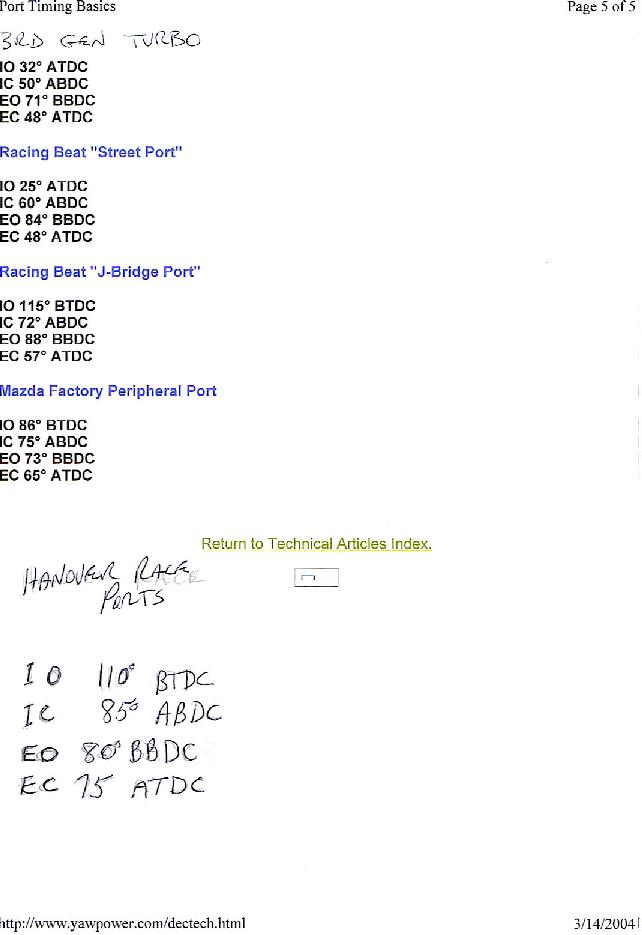
So, print off the timing events for the different engine types from Paul Yaws
web site,

http://www.yawpower.com/

 Get a magic marker and draw on the rotor housing along the location of the
apex seal for exhaust events, and along the leading or trailing edges of the
rotor side for intake events (for a side ported engine) and note how changing
the timing will change the port shape for each case.

You can also record the events from an engine ported by a third party and
compare those events to the list.

Lynn E. Hanover
The AirCraft Rotary Engine NewsLetter.  Powered by Linux.
ACRE NL web site. http://home.earthlink.net/~rotaryeng/
Copyright 1998-2003 All world wide rights reserved.