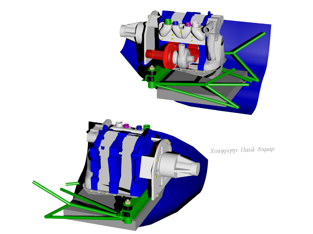
Jerry,
You may have discovered this already but the only center to center
distance you can use for the Kis MM rubber bushings is 25 inches because
of the tilt in the Kis firewall hard points top to bottom.
This assumes you are using the P51 type beam mount as shown in this
drawing. This keeps the P51 beam all in the same plane. Required
for structural reasons. I just discovered this myself. Interesting.
If the fire wall hard points were vertically aligned top to bottom any Schertz
beam width could be used with a P51 type beam mount.

I could be wrong about this but it is a little tricky to lay out.
In any event this will work as shown.

The lower beam in the right hand sketch has been rotated into the vertical
position to calculate the true length of all the tubes.

It should fit in the cowl but I will know more about that tomorrow.

Paul Lamar
Paul,

The vertical firewall height is 25.25 inches.  With the lower cowl fitted, the vertical distance from top of the firewall to the bottom center of the cowl is 28.875 inches.

Charlie Smith
KIS Cruiser 4021
OK thanks Charlie.
The lower cowl is still a couple of inches too deep in this 3D. Looks like
a water rad under the engine is not practical with the Schertz beam so you will have to
use evap cores like Tracy and Bill Schertz used. There is room of course for the
oil cooler and people seem to have more trouble with that than water cooling.

You and Bill will have to open
up the air intakes like Tracy did as there is not enough length for a proper
diffuser. It will be more like a P40 rather than a P51 cooling air intake system.
It does not seem to add too much drag as Tracy is going 217 MPH.

The old motor plate idea still works well as it gives maximum clearance under
the flywheel for a rad mounted under the engine. It is however more expensive.
Sooner or later we will have a bell housing with motor mounts so this problem
may go soon away.

I did move the KIS diagonal tube mounting points on the firewall up about five
inches and it looks like they will still clear the oil pan.

You will have to cut down the height of the water pump to get it under
the cowl. Here is the 3D and couple of pictures of my installation for reference.
the Kis Cruiser is notorious for not having much room under the top
of the cowl when installing rotary engines. Isn't hind sight wonderful ? :)

There does appear to be plenty of room along side the engine for a turbo
or a tuned tangential muffler with this P51 type beam mount.

Boeing and Airbus use Catia 3D software. I use Rhino 3D but it sure can
save a year or two for the typical rotary engine installation project in
an experimental airplane. If you don't use 3D software you are doomed
to doing it over two or more times.

Paul Lamar

The Rotary Engine NewsLetter.  Powered by Linux.
ACRE NL web site. http://home.earthlink.net/~rotaryeng/
Copyright 1998-2004 All world wide rights reserved.