Perry Mick wrote:
OK, here is DWG drawn to scale, to the nearest .05 inch as I was
able to
measure. You should be able to open this in Rhino.
The flywheel is thicker than 1/4", the prop drive is 5/8" thick so
would
act as a stiffener.

Perry
I think something like this would be safer and lighter with the
aluminum flywheel.
All the loads go into that counter-weight/flywheel-hub sooner or
later.
Unless of course you wanted to use a large diameter composite shaft
extension
like Charlie Airesman did and then I would suggest beefing up the
aluminum flywheel.
There are simple ways of doing that without adding too much weight.

Paul Lamar
Yes, I was thinking of doing exactly that, a large carbon fiber shaft
extension with a much larger hub diameter on the fan than I have now.
If
so, what would I do to the aluminum flywheel to beef it up?
Here is a drawing with the larger fan hub, longer duct exit that is
almost straight. The expanded exit area comes mostly from the large fan
hub tapering to a exit cone. There would be no rad inside the cowl, I
want to put a surface rad all around the inside of the duct exit. Maybe
adding heat to the air back there will add pressure and thrust!

Perry
OK here it is.

Paul Lamar
I think you are still going to need a bulb behind the fan to get
the outer skin of the duct more parallel with the air flow to reduce
that source of drag.

Plan: C With a larger diameter hub you could use more blade
area and keep the tip speed the same. This too would make the outer
duct skin more parallel with the overall air flow. Is this what you
had in mind above?

Also I suspect more blade area and less pitch might be an
improvement. This would have the effect of lowering the angle of
attack and C sub l to a more favorable lift to drag ratio on the
blade airfoils.

What angle of attack are your blades running at currently?

I also think the tips need to be twisted to near zero angle of attack
due to mach number effects.

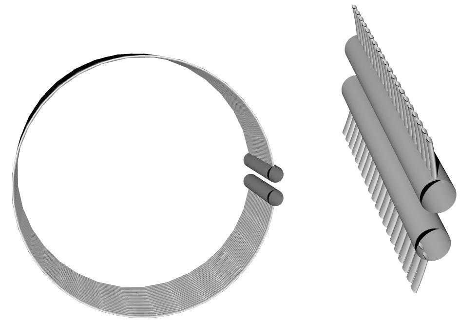
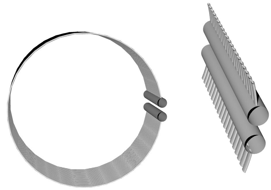
BTW how do you plan on making a surface radiator? Perhaps a long
pieces of soft aluminum tubing rolled into an oval shape and welded
to a inlet and out let manifold would work. I'll do a 3D.
The Schnider Cup racers method was to use flat sheet riveted to channels
but it was very leak prone. This is technically risky because the velocity
in the duct is higher and you may lose thrust due to increased skin
drag.
The outer wall of the duct is more parallel to direction of flight because
the duct is longer, and I made the inlet smaller. I'll send more detail on
that later. It hopefully will have lower drag because it will be thinner,
but it will also be longer.

For the rad I was thinking of two tanks, basically just 1" diameter tubes,
with npt fittings on the forward end, rear end capped off, one tank at the
top and the other at the bottom. The pressure cap would be on top of the
duct, the highest point in the system. About 30 3/16" od aluminum tubes
paralleled running around the duct on both sides between the two tanks.
Maybe numerous small aluminum fins protruding into the airstream a couple
inches, that would also function as stator blades/flow straighteners. But I
also want to see what you come up with.

You add up the volume of all those little tubes (I forget the ID now) and
it's still not that much fluid volume/weight. I think I can make a new duct
significantly lighter and the drive system/flywheel will be lighter but I
will be moving coolant weight farther aft.

Perry
That is what I had in mind. Here is my 3D. Looks expensive. I don't think it
is worth it.

What about the blade angle of attack and surface area?

Paul Lamar

The Rotary Engine NewsLetter.  Powered by Linux.
ACRE NL web site. http://home.earthlink.net/~rotaryeng/
Copyright 1998-2004 All world wide rights reserved.