What is the pitch and width of your blades Perry? RPM?

Paul Lamar
There are 3 blades, an 8" diameter hub, blade chord at the root is
4",
pitch at the root 50", straight taper to 2.5" chord at the tip,
pitch at
the tip 38". Fan diameter 37.5".
Thanks Perry. I'll try to figure out what angle of attack they
are running at unless you already know.

Paul Lamar
Here are some plots from the duct2 design file. The blade angle
information is correct for the clarky airfoil I used and that is how
I
built fan3. The angle of attack information is probably
only "relative",
as the design file had 267 mph airflow in the fanplane and 6100 RPM,
where actuals are more like 200 mph fanplane velocity and 5500 RPM.

Perry
That is interesting Perry.  I'll see if I can correct it for 200 mph
and 5500 RPM to get a handle on blade cord verses pitch.

Paul Lamar
This is what I am driving at Perry. If the angle of attack is greater
than
3 or 4 degrees at top speed and max RPM the blade is probably too narrow.
The same HP could result in more thrust with a wider blade running
at a lower angle of attack. I have evidence of this by looking at
highly optimized turbo fans.

Paul Lamar
I think I have come up with a simple way of determining optimum
blade cord. Multiply the current blade cord times the current angle
of attack and call that the "Segment Lift Number". Divide by 2 or 3
and that is the optimum blade width. I am sure Vance will jump in
here shortly :)

The theory here is the lift or thrust you get from any blade segment
is the lift coefficient times the area of the seqement. For a unit
(1) span segment it boils down to lift coef. times cord. Since lift
coef. is directly proportional to angle of attack and you know the
current angle of attack you can use that in place of the lift coef.
Are you still with me?

Now for a given lift or thrust when the angle of attack is around 2
then the lift or thrust to drag ratio is optimized for that blade
segment. The tip area is another matter. Here your priorities should
be minimizing transonic drag. Angle of attack should approach one
out here with a symmetrical airfoil and probably even swept back.
This minimizes the energy loss in the blade tip vortex. I am not
sure this is true in a ducted fan configuration.

Paul Lamar
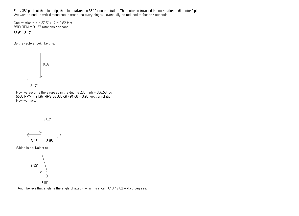
I don't think I understand you Paul, but I made up this text and drawing, to
perhaps figure out what the angle of attack is using assumed approximately
real numbers. I think it is around +5 degrees at the tip if I did this right.

Perry
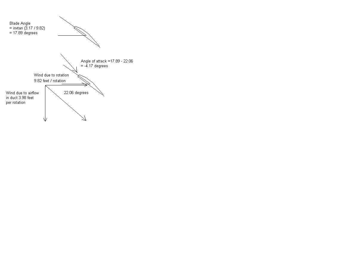
I think that first analysis was wrong. I looked at it as if the blade
were a wing standing still, and looked at the airflow towards the wing, and
it's actually a negative angle of attack. But maybe the 200 mph in the duct
is just a bad assumption and it's lower than that. We won't really know what
the angle of attack is unless I take some velocity measurements in the duct.

Perry
A few velocity measurements are in order.

Well if true IMHO the blade should be twice
as wide with half the pitch. A secondary effect is the thickness ratio
could be half. A 3% thickness out at the tip should lower the transonic
drag out there. The big guys have the advantage of 3D CFD doing fans.

I would like to hear from Vance on this.

Paul Lamar

The Rotary Engine NewsLetter.  Powered by Linux.
ACRE NL web site. http://home.earthlink.net/~rotaryeng/
Copyright 1998-2004 All world wide rights reserved.