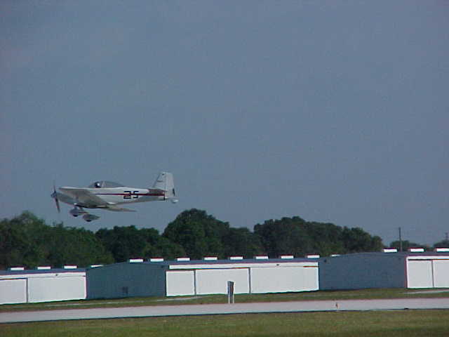
With these steep reductions you are backing into some rather large
props,
and steep
pitch numbers. With the RV7 the flight drag should be about the same
as
the
Cruiser 4 place ie with 220hp you should get about 210 mph sl max.
Putting
a 68 inch dia [in] my program suggests about a 90 inch pitch (chord
line) blade
widths
and angles about as below
blade width 30% rad  8.5 in   angle  54.5
                    50% rad 8.5 in    angle  48.4
                    70% rad 6.5 in    angle  31.4
                    90% rad  5.5 in   angle  25.2 (backing off angle
for
mach is BS)
Top and cruise are virtually the same prop and 70 % power should be
about
2300 rpm and just under 190 TAS
Vance
"(backing off angle for mach is BS)" Why? Don't just hit and run :)

Paul Lamar
Backing off the angle does nothing to reduce the Mach number, it just
reduces
the lift, and in worse case takes it to negative lift. If you are not
getting
any lift out there just cut the D*** thing off and reduce the drag. A
very
small
reduction out there can be benificial in reducing the induced drag tip
losses
but that would be a lot less than what was done to the LAEV blades. The
mass
flow per inch is really getting great out there, and it does not make
sense
to
excessively unload it.
Vance
What about the tip vortex? The tip vortex contains a lot of the energy
absorbed by the prop. Cl^2/(pi * A) It is really bad on a prop because of
the moment arm and speed of the tip. Also the tip segment drag is way
reduced
according to this plot from Von Doenoff. Again this increment of drag has
a
long moment arm.

I would like to see a plot of torque absorption as a function of radius.
I suspect the majority of it happens out near the tips.

BTW do you have a plot of angle of attack as a function of speed at some
constant
RPM for the prop design you just uploaded?

Paul Lamar
Paul - My prop design approach is to attempt to have a uniform hp per square
inch
over the working disk area. Every thing inside of the .2 rad is ignored
(your spinner
should be that big) Tip vortice is a loss, but it is not "a lot of the
energy" The Von Doenoff
data shows min drag not too far off .2 Cl where the tip will be close to at
design point.
Going to a negative lift coeff to reduce drag is really dumb - your
lift/drag ratio is negative
for darn sake!. Torque absorbtion is not the measure - it is power
absorbtion wich tries
to be uniform - a radiused back tip, with long trailing edge is probably
better than
a "clipped" tip - just as it is for a wing - a prop is a wing! I do not Know
what Bill
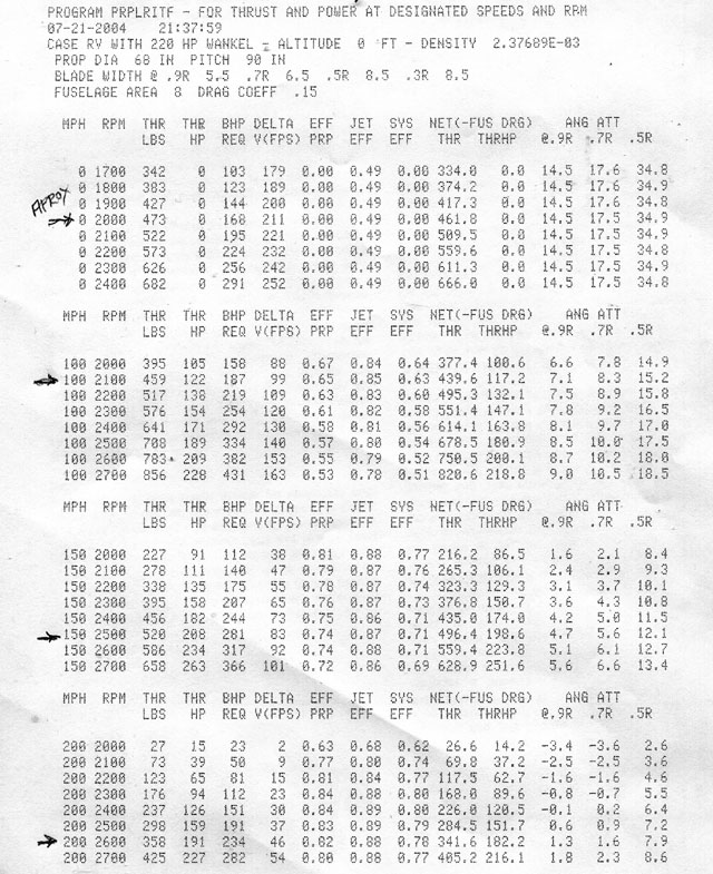
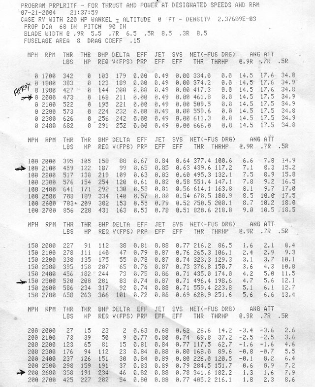
is trying to show in that table but here is the prop over a few intersting
points
with things like rpm, thrust, and hp clearly labled. It looks like the prop
I sized
is a bit "big" trim blade area perhaps. I looked at an RV the other day and
it appears
it could swing 72 in dia OK which would be a big help.
Vance
Torque at a given RPM is HP. You know that :)

I think I may have used the wrong term. What I meant was angle of attack
should go to zero at the tips. Not the pitch.

Tracy is flying a 73 inch prop with his 2.85 gear box on his RV4 and he has trouble
holding it steady on takeoff.

The RV8 has more prop clearance.

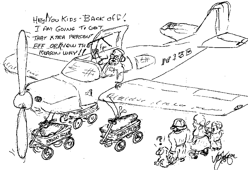
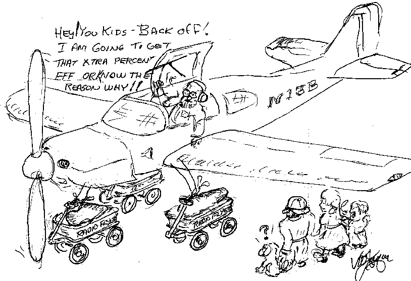
You used to give me a hard time about long props. Here is your cartoon on the
subject in case you forgot :)

Thanks for the table. That clears up a lot.

Paul Lamar

The Rotary Engine NewsLetter.  Powered by Linux.
ACRE NL web site. http://home.earthlink.net/~rotaryeng/
Copyright 1998-2004 All world wide rights reserved.