Historical perspective on the internal spur gear PSRU.

Vee s for Victory by Daniel D. Whitney Schiffler Military History.

Reduction Gear Limitations.

>From the beginning the power limiting component
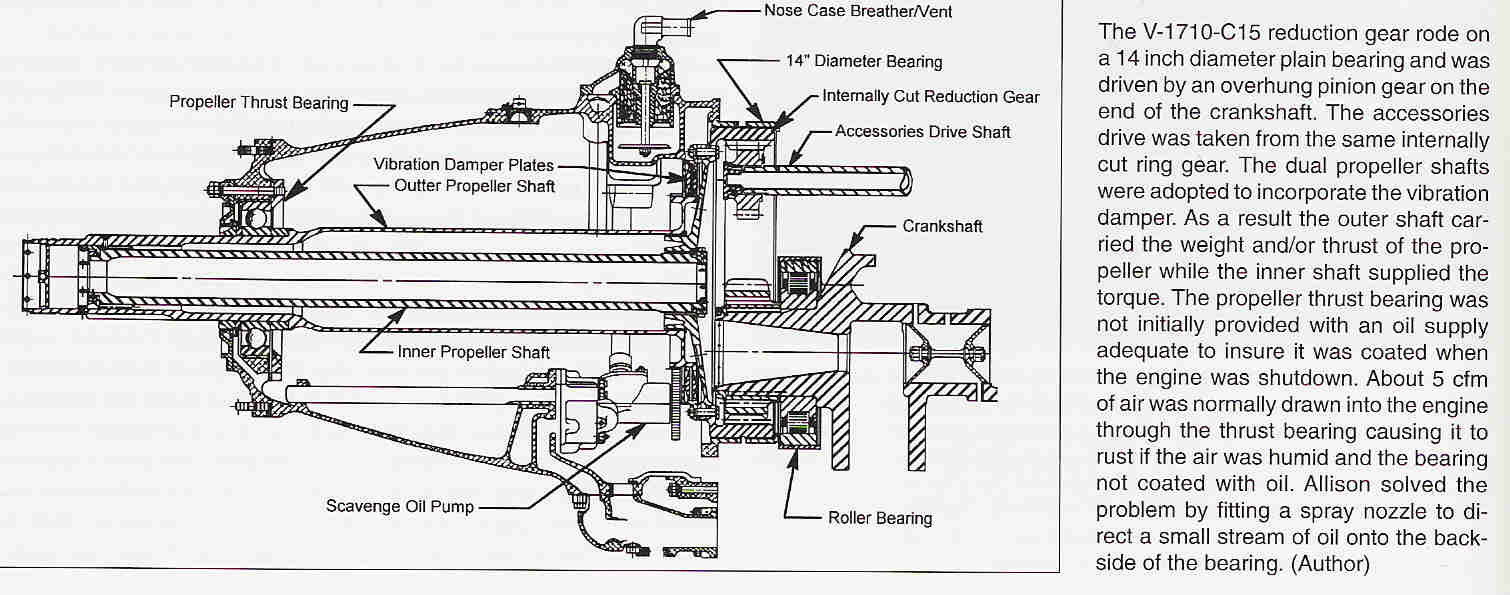
in the V-171 O-C engine was the propeller reduction gear assembly. In the
effort to provide the maximum amount of streamlining, (and it was believed
to get the lightest reduction gear), Allison had utilized an "internal" spur
gear design driven by an "over-hung" crankshaft pinion. The "driven gear"
was set in a necessarily large diameter ring gear with "internal" teeth.
This in turn was supported by a large "plain" bearing, fourteen inches in
diameter. With the engine qualified to run for short periods at up to 3700
rpm, the sliding velocity in this bearing was an extremely high 13,561 feet
per minute, or 154 mph. To keep everything working smoothly Allison directed
almost 1/3 of the engine oil supply, at a pressure of about 75 psig, into
the bearing.  Still it was enough of a concern that early development
engines were equipped with a bearing temperature indicator. If the
temperature increased abnormally it was time to significantly reduce power
and soon land. All of this meant that there was a limit to the amount of
power that could be reliably transmitted. The value was set at 1150 bhp,
though the V-171O19(C13) Hi-BHP test successfully operated at up to 1575 bhp
at 3000 rpm.

Allison was quite adamant about not overpowering the V-171O-C15 engine,
stating that "on account [of] extreme over-load on [the] over-hung pinion at
the higher horsepower's involved" in operating at takeoff manifold pressures
up to the critical altitude of the engine. The limitation was not the
bearing, but rather the bending stresses developed in the front cheek
of the crankshaft as a result of the high loads transmitted to the
crankshaft extension carrying the pinion gear.

In early 1935 Wright Field asked Allison to investigatl the feasibility of
designing a reduction gear with conventional bearings for the engine. Such
a unit was designed, and included provisions for a bearing to support the
outboard end of the crankshaft and thereby eliminate the troublesome
bending loads on the front crankcheek. Unfortunately, considerable redesign
of the engine would have been required including not only the new reduction
gear assembly, but sig nificantly, new upper and lower crankcases, new
crankshaft accessory drive system and considerable revision to the detail
parts. While the design was proposed for fitting t( the X/YV-171O-3 and
XV-171O-5 engines, it was determine( to not be practical during the Type
Test period. With the opportunity to completely redesign the engine
following the Type Test in 1937, these features were incorporated in the "E"
and "F" series engines, which used straight cut "external" spur gears. As
developed, the ElF design followe( closely the 1935 concept, and resulted in
lighter and more compact reduction gears than the original "c" gear set. This
created a higher "thrust line" that reduced frontal area. Allison got their
start in the engine business by building high powered gearing and drives,
and these reduction gears benefited from all of that experience.

In September 1940 the Air Corps issued a Technical Order specific t( the
early production V-17lO-C/D engines. It required inspection and re working
of the reduction gears on overhauled engines that had had any of their gears
that mated with the large internally cut reduction gear replaced. Allison was
having trouble maintaining tooth profile on the internally cut teeth. If
galling or burring was found, the fix required hand stoning of the damaged
tooth faces following by further running the engine, disassemble and
re-inspection. Evidently a similar procedure had been followed dur ing
original manufacture an assembly of each engine.

Within months of introduction into service on the P-40, reports of rust and
corrosion in the V-171O-33(CI5) reduction gear began coming in. Thc problems
were in the Propeller Thrust Bearing and also between the twc propeller
shafts. As early as January 1941 Allison acknowledged that excessive
pitting and rusting of the Propeller Thrust Bearing was occurring.

The problem appeared to be due to the location of the gear case vent, and
the resulting high crankcase vacuum.53 The consequence was that it was
impossible for any oil vapor to reach this bearing, coupled with humid air
being drawn in as the engine cooled following normal operation. It was found
that lubricating oil was not adequately wetting all of the surfaces of the
propeller shaft and rear face ofthe thrust bearing. In early March 1941
Allison conducted a test program of different nozzles that would direct a
stream of oil onto the surfaces prone to rusting. They devised a field
mountable external tube and nozzle assembly that obtained its oil supply
from the pressure line in the governor pad, and for production engines, a
similar nozzle was mounted inside the reduction gear assembly accomplishing
the same thing.

No effective fix had been implemented by the time the engines for the AVG
were built. Consequently, when the AVG began their operations in the humid
jungles of Burma they immediately began to observe rusting. During October
1941 the Allison representative to the AVG devised his own fix and tested it
on the firstAVG assembled airplane, P-8124 with V171O-CI5 AEC #946. This
engine had already developed a rusty thrllst bearing. He installed a
stainless steel dam in the bottom of the gear case.  The purpose was to
retain a pool of oil sufficient to insure everything was oil covered, though
it required hand rotation of the prop after cooldown to completely wet the
bearing. This worked quite well for the AVG, but required the ground crew to
hand rotate the prop at the end of each day, as well as prior to startup
every day. Allison also incorporated a production procedure to cover the
two concentric propeller shafts with soft grease.  This succeeded in solving
that portion of the rust problem.

Hopper Oil Tank and #6 Main Bearing Failures

The Army Air Corps' original PAO's, and some of the early P-40B's, were
built with "hopper" type oil tanks. These were adequate for positive "g"
operations, but negative "g" would deprive the engine oil pump of its source
of oil, as all of the oil would be at the "top" of the hopper. The highly
loaded bearings in the V-17l0 demanded a constant supply of high pressure
oil. Allison maintained that when the oil supply was interrupted the heavily
loaded number 6 main bearing (the one at the front of the engine) would
quickly "wipe", allowing metal-to-metal contact and soon result in a failed
bearing and broken crankshaft. The British Tomahawks had a different
oil tank, one with a pendulum type pickup that was free to "flop" from the
bottom to the top of the tank during periods of negative "g".  These tanks
were to be retrofitted onto the Air Corps airplanes, but the work was slow
to be completed. Fortunately the British in North Africa and the AVG in
China-Burma all used British contract Tomahawks and did not have the
problem.  Lockheed P-38 models prior to the P-38H were originally equipped
with hopper type oil tanks and would also suffer damaging loss of oil
pressure drning certain maneuvers. Many of these early P-38's were being
used within the U.S. in training roles, and as late as January 1943 there
were no plans to retrofit the pendulum equipped tanks. The result that the
loss rate of engines and aircraft was unnecessarily high.

The Rotary Engine NewsLetter.  Powered by Linux.
ACRE NL web site. http://home.earthlink.net/~rotaryeng/
Copyright 1998-2004 All world wide rights reserved.