Jesse Hilton wrote:
Does anybody have any info/pics on the Volvo
turbocompound D12D-500?  It uses a Holset HX55 and
a
HP72. I have no idea of the weight or size, but
was
wondering if this could be adapted to a 20b. I
have
no idea of the Volvo engine's flow numbers let
alone
any compressor maps.

For those of you looking into the turbo-generator,
check out this link:

http://www.osti.gov/fcvt/deer2001/gerke.pdf
Jesse Hilton wrote:
Here is the file.
Wow!!! I did not see this before I made my suggestions, Honest. Great minds
work in similar fashion :) The problem with the diesel is it already too
efficient to get much out of turbo compounding. Never the less Caterpillar
has been at the forefront of this technology for many years having built
and sold many turbo compound diesel engines.

As I said, a sea change is about to occur in automotive ICE engines.
Doug you might want to pass this on to Mazda.

Paul Lamar
Jesse Hilton wrote:
Volvo and Scania make big rigs in Europe (from what I
gather, never been there.)  They both are using
turbocompounding and getting improved fuel economy at
all speeds and power loadings.  This is recent from
what I have read.  Volvo first selling turbocompound
desiels in the early 90's with a few problems.  By
about 1998 they had most of the bugs worked out.
Infortunately, I only speak/read english so there isnt
much info out there for me.

But, I just found this link:

http://www.scania.com/products/r_series_trucks/technology/turbocompound/
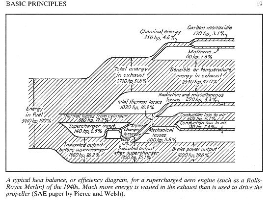
I cannot overemphasize the importance of this work being done by Caterpillar.
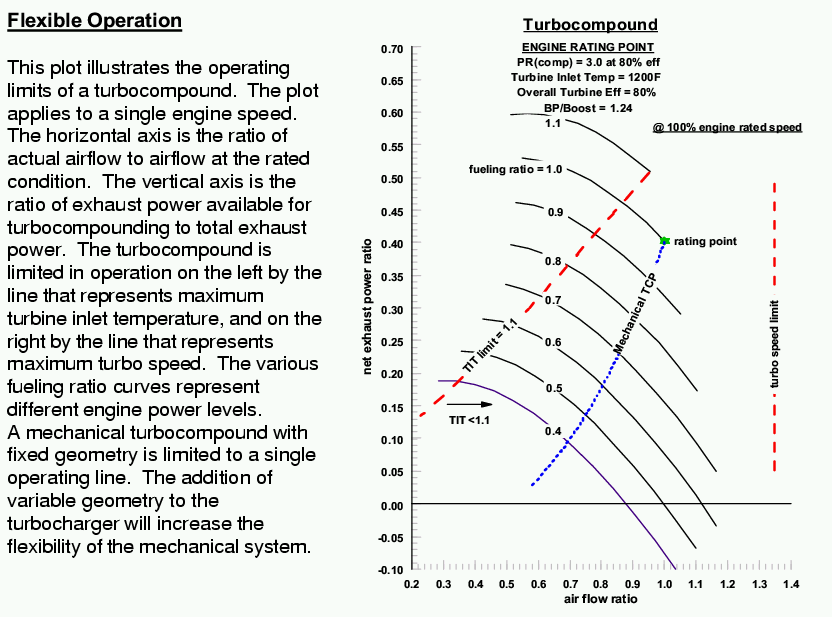
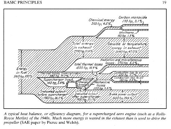
This chart shows that up to 50% of the waste energy in the exhaust
can be recovered by high efficiency mechanical means. Perhaps a light weight
variable ratio 10 or 20 HP turbo compound gearbox will be needed. The electric
solution is marred by the less efficient generator and electric motor.

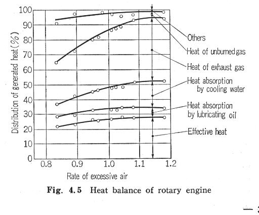
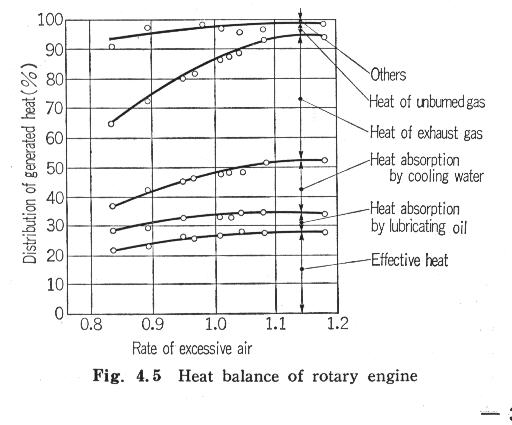
Here is the chart again. Here too is the heat balance of the rotary engine.
Typical for all ICE engines. 50% of the 50% of waste energy in the exhaust
is an overall 25% improvement in the overall efficiency of the internal combustion
engine. Again I cannot overemphasize the importance of this work world wide.

Paul Lamar

_______________________________________________________________________
Diesel Engine Waste Heat Recoverv Utilizing Electric Turbocompound Technology

Background

This cooperative program between the DOE Office of Heavy Vehicle Technology and Caterpillar, Inc. is aimed at demonstrating electric turbocompound technology on
a Class 8 truck engine. This is a lab demonstration program, with no provision for on-truck testing of the system.

The goal is to demonstrate the level of fuel efficiency improvement attainable with the electric turbocompound system. Also, electric turbocompounding adds an
additional level of control to the air supply which could be a component in an emissions control strategy.

Mechanical Turbocompounding

Existing turbocompound technology consists of a conventional mechanical turbocompound system. The system includes a conventional turbocharger which recovers
exhaust energy in a turbine to boost the air coming into the engine in a conventional fashion.

Downstream of the turbocharger turbine, the exhaust gas goes through a second turbine. The energy recovered here is added to the engine torque through a system
of shafts, gears and a fluid coupling.

The objective of this program is to demonstrate the recovery exhaust energy electrically by using high speed generator technology. Electric turbocompounding
eliminates the mechanical coupling to the engine crankshaft necessary in mechanical turbocompounding. This provides more flexibility in packaging. The electric
turbocompound system also provides more control flexibility in that the amount of power extracted can be varied which allows control of engine boost.
Also, the generator can be operated as a motor to spin up the turbo more quickly to improve turbo response. The electric turbocompound is a natural fit in a
vehicle equipped with More Electric technology.

Caterpillar is using past experience in mechanical turbocompounding to aid in developing the electric turbocompound system. The high performance turbomachinery
will be married with emerging high-speed generator technology.

Program Overview

The program has started with the development of a concept of the entire system, and continues with design and procurement of components.

The components are then bench tested individually, and as a system.


The final step is an on-engine lab test to demonstrate fuel efficiency gains with tu rbocompoundi ng.

More Electric Truck

More Electric Initiative technology can be applied to an on-highway truck. Accessories that are normally driven by a belt or chain off the engine are
electrically driven. Accessories can be installed where packaging and servicing are optimized. Also, accessories can be run only when needed at the required
power level. A key component of the MEI truck is the crank starter/generator.
This device replaces both the generator and the starter on a conventional truck engine. The crank starter/generator can also be used as a motor to convert
electric power to driveline torque power.

Electric turbocompounding is a complementary technology to MEI in that the electric power generated by the electric turbocompound can be used power the ME I
accessories. The electric power can also be added to the power train through the crank starter/motor/generator. Likewise, the flow of power can be reversed to
power up the turbocharger if needed.

Electrical System and Control Development

At this state of development, we still have a number of significant issues to resolve. Much of them deal with applying high speed generator technology to this
environment.

The practicality of the system will be determined, in part, by the additional cost and size. Applying this technology to an engine environment is a concern.
Suppliers of high speed generators have experience at this level of speed, but not at the power output level needed. The high frequency of the generator output
is also challenging. The added flexibility of the electric turbocompound system makes controlling and optimizing the system more complicated. Requiring one
turbine to drive both the compressor and generator makes this a highly loaded turbine stage.

Now, let's take a look at the overall system. On the turbocharger we have a high speed generator producing electricity to a common voltage bus. The power can be
applied to the motor on the engine crankshaft. Keep in mind that either of these electric machines can be operated in motoring or generating mode. Also, the
turbine-generated power can be used to power attached electrical loads, i.e., MEI accessories, or applied to energy storage devices like batteries,
ultracapacitors, etc.

We also have an overall control system that interacts with the engine controller.
We are controlling the amount of electrical power that is produced and consumed, subject to constraints in exhaust temperature, boost pressure, turbo speed, and
the like.

To aid in performance prediction, system optimization and control development, a computer simulation model of the engine system was developed. Production engine
test data were used to calibrate the model. Then maps of the electric turbocompound system were added to the model to simulate the electric turbocompounded
engine. The simulation model was used to investigate control system strategies.

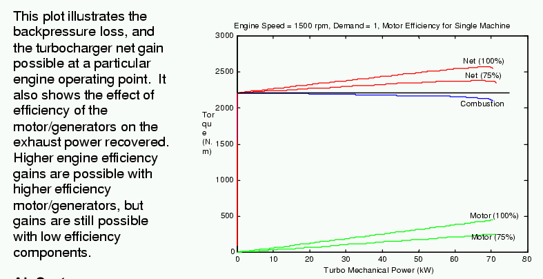
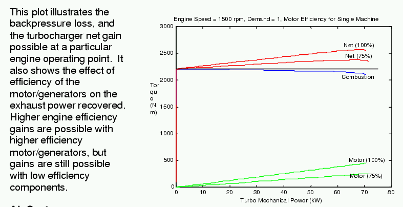
The engine simulation model was also used to predict the efficiency gains obtainable. The addition of turbocompounding increases exhaust backpressure on the
engine. This results in a drop in engine performance. The turbocompounding adds additional power back to the engine, more than compensating for the backpressure
loss. The simulation model has been used to predict efficiency gains a different engine operating points.

This plot illustrates the backpressure loss, and the turbocharger net gain possible at a particular engine operating point. It also shows the effect of
efficiency of the motor/generators on the exhaust power recovered. Higher engine efficiency gains are possible with higher efficiency motor/generators, but
gains are still possible with low efficiency components.

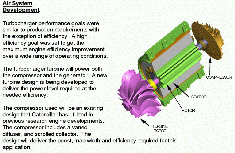
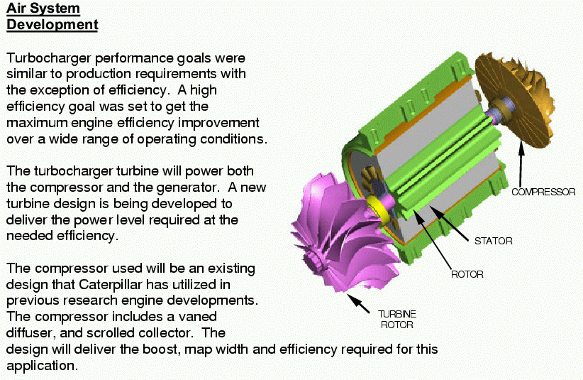
Turbocharger performance goals were similar to production requirements with the exception of efficiency. A high efficiency goal was set to get the maximum
engine efficiency improvement over a wide range of operating conditions.

The turbocharger turbine will power both the compressor and the generator. A new turbine design is being developed to deliver the power level required at the
needed efficiency.

The compressor used will be an existing design that Caterpillar has utilized in previous research engine developments.
The compressor includes a vaned diffuser, and scrolled collector. The design will deliver the boost, map width and efficiency required for this application.

TURBINE ROTOR

The current shaft design concept includes the generator rotor mounted between the turbine bearings. Rolling element bearings will be used to maximize efficiency
and shaft dynamic stability. Preliminary shaft dynamics analysis indicates that meeting shaft dynamic requirements will be a challenge. As the turbo and
generator rotor designs continue to be developed, shaft dynamics will be a major consideration.

Motor/Generator Development

Development of the high speed turbo motor/generator is underway. Candidate technologies are being evaluated before proceeding with design.

The crank starter motor/generator will utilize the design from the MEI truck program. An investigation is being made into the practicality of modifying the
design so that the crank motor can absorb 100% of the power produced by the turbo generator.

Summary

Thus far in this program, the system architecture has been identified. A system model has been developed and validated which is being used to develop the
control strategy. The requirements for the air handling system have been determined, and paths to development for the components have been established. The
design of the high speed motor generator is underway, beginning with evaluation of available technologies. Performance predictions at important operating points
have been made showing signif


_______________________________________________________________________

The Rotary Engine NewsLetter.  Powered by Linux.
ACRE NL web site. http://home.earthlink.net/~rotaryeng/
Copyright 1998-2004 All world wide rights reserved.