Scott Gettings wrote:
Paul & group:

A while ago you graciously answered some early questions about 13B mounts in a Glass Goose.  To recap, the Goose is a pusher  with  a cutout in the upper wing
for the engine and mounts, and a very narrow rear pylon.  The summary of the previous thread was to have a front mount (water pump end) as wide as possible
using a 12A front cover, and some type of rear, Schertz beam.

I've obtained a 12A front cover, a 6061x1/2" plate for the front mount main beam, and a RWS motor mount plate (thanks, Bob White!).  I have some crude wood
mockups of some front mount options to present.

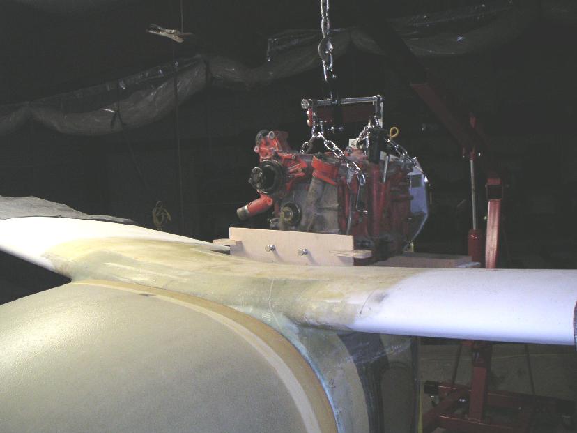
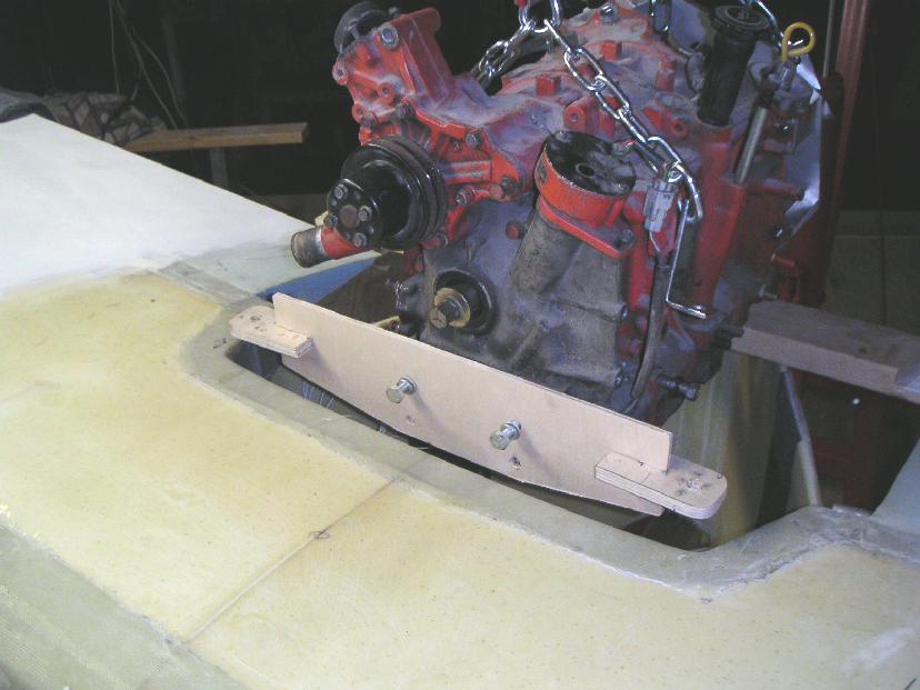
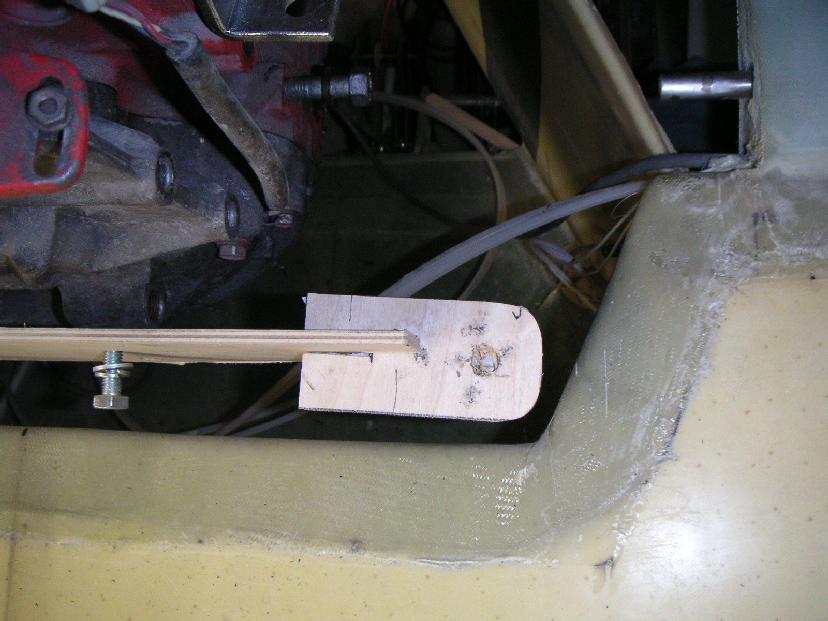
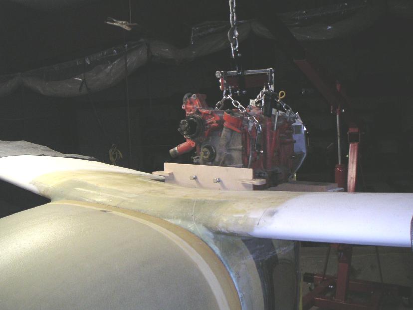
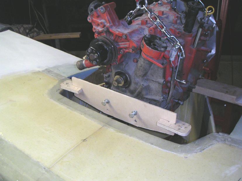
The Goose upper wing cutout is 22" wide at its narrow point, which will just allow 20" between the front mounts.  The first pix on this message show a
"horizontal tab" mount mockup, based on Paul's front mount layout.

One problem with this version is that it forces the engine about an inch aft  - not good.  Another  is the wood/composite mount support will interfere with
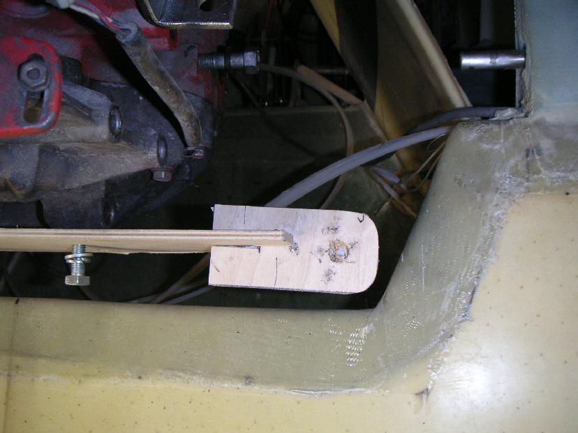
the aluminum main beam, because the composite structure will need a vertical box underneath  to support its horizontal part.  If the horizontal aluminum tab
can only cantilever out 1", then it isn't quite long enough to allow the Barry/bolts/washers to fit within the composite structure.  If the aluminum
horizontal can handle the load with the bolt hole being about 1 1/2" out from the end of the vertical metal, then it would just fit.

Perhaps a better option might be to allow the engine to move as far forward as possible, and use a piece of angle bolted on the aft surface of the primary
beam to hold the Barry mount.  This would place the Barry mount behind the beam (see pic) and help the CG issue.  Since an angle could be bolted with its
surface below the primary beam, there would be no interference with the composite structure underneath.

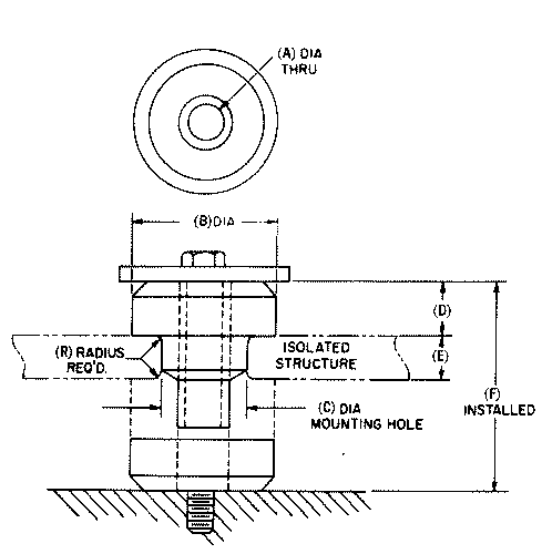
Another solution might be to place the Barry mounts vertically (see pic), but this would place all the torque on the mount's radial axis -- probably no good
(but easy to build the mount).
My specific questions on this front mount are:

1. How far can a 1/2" 6061 horizontal tab cantilever out from a vertical plate and still handle the relatively low loads of this front mount?
Thanks very much in advance.  I'll have another posting on the rear mounts.

Scott Gettings
Lets take this one step at a time over the next couple of days.
Too confusing for me otherwise. I'll be gone tomorrow anyway out
in the desert looking over our video shoot location.

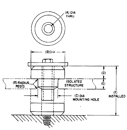
The Barry mounts are not really designed to take high radial loads.
If at all possible rotate them 90 degrees so the down load is axial.
Don't use a 1/2 inch thick plate for the front mounts. Use 1/4 thick
3 by 3 angle with the axial direction of the mounts vertical.
This should bolt directly to the 12A front cover. Very simple.
No need to make it three pieces as shown in your pictures.
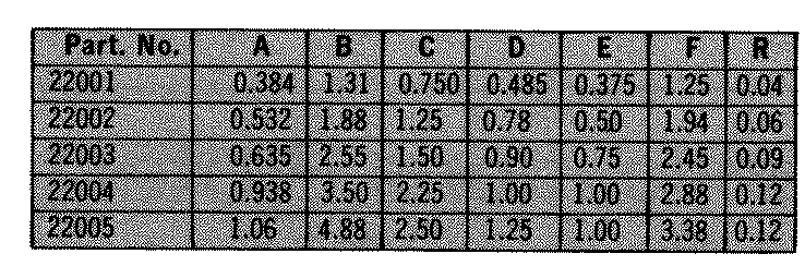
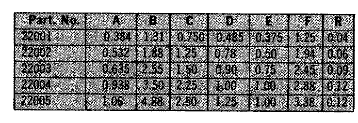
Use two of the 22001 series. Cut off the excess material
from the 3 by 3 angle. Total vert load is about 50 pounds.
25 pounds per rubber mount. Thrust load will be shared by
all four mounts.

Paul Lamar

The Rotary Engine NewsLetter.  Powered by Linux.
ACRE NL web site. http://home.earthlink.net/~rotaryeng/
Copyright 1998-2004 All world wide rights reserved.