Thanks again Paul.  No problems with the prop location or cowling within
these few inches.

We discussed Rino's installation in the past - we communicate regularly.
HIs method requires 2 bridges (extra weight and complexity), special
engine
center mounts, and only has about 14" of inter-mount width at the very
most.  Another Goose builder had to add 12 lbs of ballast in the nose to
compensate for his 13B that was mounted 4" behind the wing cutout!  The
battery is already in the nose.  The Goose is unfortunately an aft-CG
prone
plane, which is why no one is using an 0-360 instead of the slightly
lighter 0-320.  So the CG issue is fairly important.

Thanks for the front end housing mounting idea -- that might work.
Perhaps
I also could use a longer 1/4" angle (4x3") turned around so the
horizontal
part was facing aft, yet was low enough to clear the front housing?
This
option might place the mounting plane too low on the wing cutout,
however.
I'll check it out.

If none of these options are working, is a flat plate on the 12A front
cover with bolted-on, rear-facing angles a viable possibility at all?  I
realize that the 1/2" plate is overly heavy, but are there other reasons
this won't work?  This option would handle the CG issue and allow the
composite mounts to be placed in an ideal spot because the location of
the
angles would not be fixed. It this might work, and 1/2" is overkill,
would
a 1/4" or 3/8" x 3" flat plate be more appropriate instead?  I will
certainly static load whatever I end up with.

Thanks again,

Scott Gettings
For the front mount 1/4 inch plate would be plenty.

Here are a few more ideas that Rhino Lacomb came up with.

These are mostly for the rear mounts.

CG_Mount_design2.gif is the best IMHO.

Paul Lamar

Thanks again, Paul.

These are the drawings I originally submitted for consideration a while
back (along with Rino's mounts). You must have a great filing system to
keep track of all of these!

The first drawing will interfere with the starter, which is no good.  The
second one (you liked) relies on mounting to Tracy's plate alone -- which
he says will void his warranty.

I suppose I could mount this plate on the engine side instead, with a side
angle plate bolted on to pick up some oil pan bolts. You said the mounting
should be as close to Tracy's plate as possible.  Moving this plate to the
engine end housing location is almost 3" farther away from the prop than
Tracy's plate.

I'm assuming 1/2" 60601 is sufficient for both the vertical and horizontal
structures in this rear mount option. Can a vertical plate for this mount
be thinner?

At the risk of being a pest, there are two other final items:  Which Barry
mount (or its axial load) is best for the rear? You mentioned 150 lbs
might
be OK in the past, but all 4 were going to be the same.

And, if there is a choice, is it better for the rubber mount to hold the
composite structure or the metal? It would seem that the composite mount
might wear better if held by rubber instead of metal??

I'll drive my Ford Explorer's front end on top of this one to test it!

Thanks a million!

Scott Gettings
My filing system is not bad but keeping track of who sent the pictures and
drawings
is not as good. I use Xtree for Linux. We all need to put our name on our
drawings.

Tracy says that just to cover his butt but Dave Leonard is flying with
something similar
adjacent to the engine. The CG of the Eng/PSRU/Prop combination is closer
to the engine than it
is to Tracy reduction unit anyway. It does not need to rely on Tracy's
plate. Just
Tracy's spacers are shortened by 1/2 inch.

On the other hand what Rino used for an aft mount does rely on Tracy's
plate.
Here it is again.

With all due respect Tracy should add some motor mounts to his plate and do
us all a huge
favor. We would then not have to go through all this stuff over and over.
George is supposed to be doing a cast bell housing with motor mounts but he
has
not mentioned it much lately. We still need it George. A bell housing with
bed type mounts is a lot easier than redoing the whole front of the engine
for Lycoming dynafocal type mounts. Hint hint Francois :)

Speaking of bell housings with bed type mounts here is how CJ Smale made
them
on his Defient. He was WAY ahead of his time.

Paul Lamar
I assume that this bell housing is known to the group?  Too bad it doesn't
have mounts already in place.
http://www.atkinsrotary.com/store/customer/product.php?productid=16761&cat=586&page=1

Scott Gettings
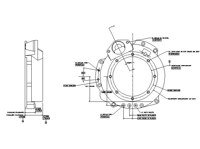
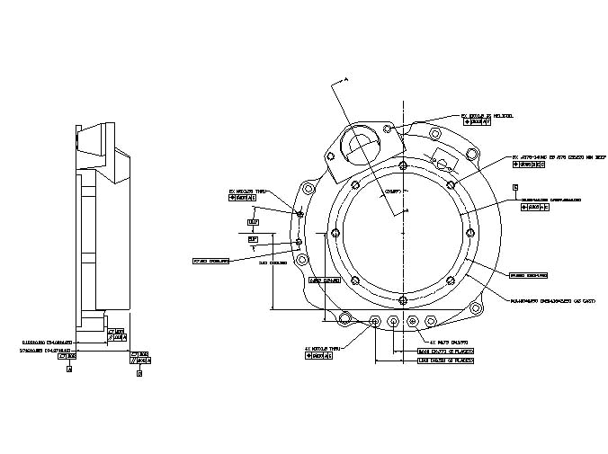
That is a marine bell housing near identical to the Rotary Power Marine version
and will not fit Tracy's gear box. George's bell housing is designed to fit Tracy's gear box.


Tig welded fabricated custom mounts can easily be bolted on to George's
flat sided bell housing giving lots of design flexibility.

Paul Lamar


The Rotary Engine NewsLetter.  Powered by Linux.
ACRE NL web site. http://home.earthlink.net/~rotaryeng/
Copyright 1998-2004 All world wide rights reserved.