Douglas Fir wrote:
Everyone

Turbo compound project. Report #2

With the turbo 13B engine safely in my workshop I am starting to plan the
research project for turbo compounding it. After rebuilding the engine with
new seals, and putting Tracy's EC-2 unit on it. I'll  leave the engine in
its stock condition (yes running on gasoline) with only the alternator and
water pump, connected  during primary testing.

The first dyno testing (after I assemble the dyno) will be to determine
baseline BSFC data for this particular engine at different power settings.
I already have a small 25 channel data logger made by PICO in England that
interfaces to the PC through the  RS-232 port.

The second phase of testing will be to design and make  a turbo compound
system using the standard turbo and  see if I can document an improved BSFC
with the same test variable loads.

Please jump in with your thoughts and correct me if I am wrong or help fill
in the ? marks.

IMHO:

It is safe assumption to say that the majority of homebuilt aircraft owners
are very concerned with improving fuel economy.

A standard turbo is sized to provide boost and waste the exhaust gas in the
high MAP situations and hopefully before the engine starts knocking.

Common aircraft economy cruise ranges are from 55% to 75% power.

At these power settings  not a lot (if any ?) exhaust energy leaves via the
waste gate. We need to find a way to measure the actual torque real time
that is leaving the turbo shaft and would like to hear any ideas.  Turbo
tach and torque sensor. transducer?

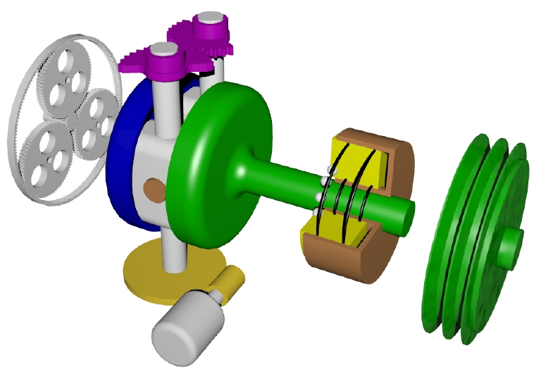
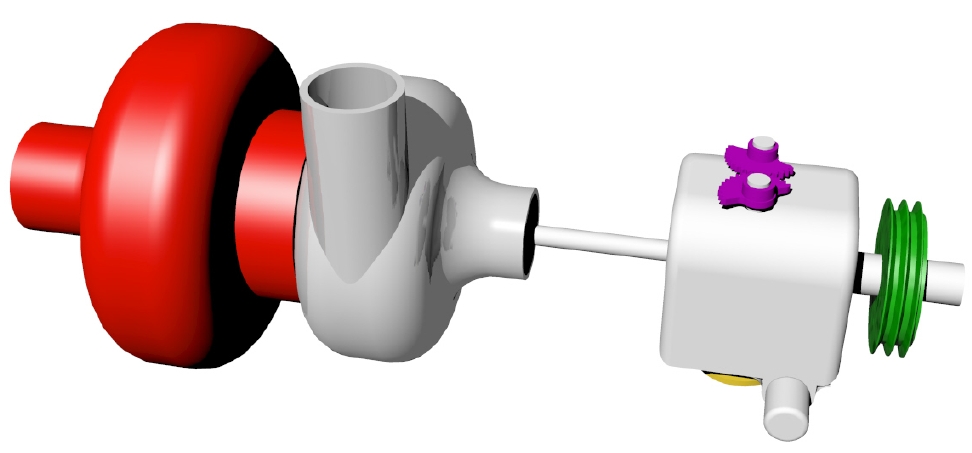
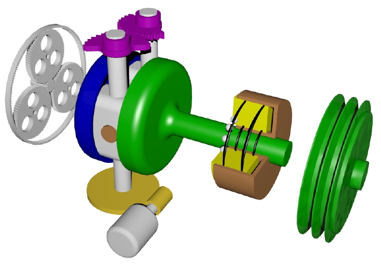
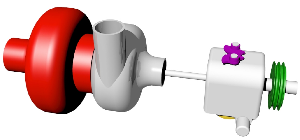
Stealing energy from the standard turbo/compressor, diverting it through a
CVT and delivering it to the  e-shaft via a belt drive will become a
lose/lose/gain? situation. In short many variables come into play at almost
real time.

Lets say we steal 20% of the energy from turbo and send it to the e-shaft.
We still have 80% to use for the boost compressor though.  When lowering the
boost by 20% it lowers the air/fuel amount but perhaps not by 20%?. For a
moment we could say the Hp is also lowered and assuming we didn't touch the
C/S prop setting, the engine rpm and hence turbo torque would go down.
However simultaneously we are  applying  90% of this 'borrowed' torque (10%
loss through the CVT) thus adding a boost to the e-shaft.  Logic would
dictate we are borrowing from Paul with interest to pay Peter. We are in a
losing proposition and it would seem that our system would rapidly
degenerate into  becoming an engine brake as the rpm decreased even more. Of
course rpm, Hp. and boost curves are not perfectly linear.  We may find a
sweet spot.  But likely not.

Our experiment will fail.  Fine but we expect that. Now we look at the data
and see where we failed the least.  Even with the standard turbo there is
bound some turbo range that is a little less bitter in defeat. We then know
what to improve. For starters I would think we would have to get the CVT
operating well over 95% efficiency.

Moving on:

 Logically the best rpm to transfer power to the e-shaft would be at the rpm
or manifold settings that causes the turbo waste gate to open. High power
setting? Not so good for economy though because of the high drag effect on
our airplane at high speeds. Forget for a moment we may be above 10K' where
the  thrust/drag ratio becomes more beneficial to BSFC in  some planes.

Thus:

The ideal situation will be to use an over sized turbine that has energy to
waste so to speak. One that is specifically designed to take advantage of
the rotary engine's dynamic boost.  In short a very efficient turbo motor.
The unit will be determined by size, weight, performance. It might? need
moveable vanes in the intake to improve the compressor's compression ratio
at lower speeds or keep a boost setting through a wider (slower) RPM range.
With the oversized turbo we will at least have more wasted energy to play
with. We can then have our cake and perhaps nibble it too.  Turbo
compounding is not the technology to let us go fast and sip fuel. At best it
will let us have our full boost climb out and full throttle dashes  with a
small  addition of torque to the eshaft.

I am betting it is somewhere in the  cruise ranges that this idea will
shine. With a CVT we can dial in what percent of the turbo motor power goes
to the compressor or e-shaft. No more waste gate 'wasting' an available
resource.  Best 55% cruise might have only a small air boost with most of
the energy going through the turbo compound? Don't know. Have to test it.
Bound to be some surprises. At what point does a low BSFC  happen in your
airplane with this device?  That will depend upon your altitude, power
setting, type of airplane, prop and rpm setting.

For me that life saver cruise speed could be lower than 50% power when
encountering headwinds more than halfway into a  2000 mile leg over cold
waters.

With some success and a lot more failures we can make an educated guess on
how to size the turbo-compound system for the 20B, which is the engine I'll
eventually use.

Doug in Japan
Doug, I got the gear catalog from QTC Gears and I suspect it is the same
as the KHK catalog. http://www.qtcgears.com/Q410/QTC/Q410P344.htm

I found a pinion/shaft and gear that will give us a pitch line velocity
of 15,500 ft/minute at 100K RPM which is an improvement over my first and
second iterations. Since the V22 Osprey gear box is running at 25,000 ft/minute...
15K ft/min is a rather low number. (See this pdf for more info on high
speed gears. http://gltrs.grc.nasa.gov/reports/2002/TM-2002-211336.pdf )

The KHK part number is SSGS1.5-10 ten teeth, PD is 15 mm or .59 inches.

It was driving me crazy trying to figure out a first stage planetary configuration
using this pinion/shaft and off the shelf ground precision planet gears so I
wrote this QB program to help me out. The last column checks to
see if a three planet configuration is even possible. If the last column is
an integer it is possible to build a high reduction ratio 3 planet
planetary using the planets with that number of teeth.

Bottom line is about the only off the shelf high precision planet gear we can use is the
KHK MSGA1.5-50. A 50 tooth, 1.5 module gear with a PD of 75 mm or 2.952 inches.
this gives us a 12:1 reduction for the first stage or at 100,000 RPM turbo charger
input 8,300 RPM output and in to the CVT. This is of course going to require a custom
ring gear with 110 teeth and a PD of 165 mm or 6.496 inches. I'll do a 2D drawing
shortly.

Now I need help from you oil engineers. I am looking for the specs
on synthetic oil and how it relates to standard gear oils. I suspect
synthetic oil will work much better at these high pitch line velocities
than traditional oils. There is such a thing as Kinematic Velocity
and I need to know what that is for say, Mobile One.

Paul Lamar

The Rotary Engine NewsLetter.  Powered by Linux.
ACRE NL web site. http://home.earthlink.net/~rotaryeng/
Copyright 1998-2004 All world wide rights reserved.
CLS
'mod 1.5
OPEN "planet.dat" FOR OUTPUT AS #1


PinGearNoT = 10
PRINT #1, "PinGearNoT ="; PinGearNoT
DiaPin = 1.5 * PinGearNoT
PRINT #1, "DiaPin ="; DiaPin
PRINT #1, "DiaPin Inches ="; DiaPin / 25.4
'PRINT #1, "DiaPin Inches/2 ="; (DiaPin / 25.4) / 2

PRINT #1,
PRINT #1, "Planet Gear  Ring Gear   Dia Ring    Ring Gear  "
PRINT #1, "No Teeth     No Teeth    Gear Dia.   Dia. Inches    Ratio       3 Planets"

FOR PlanGearNoT = 35 TO 70 STEP 1

RingGearNoT = PinGearNoT + 2 * PlanGearNoT
PRINT #1, USING "###"; PlanGearNoT;
PRINT #1, USING "##############"; RingGearNoT;
DiaRing = 1.5 * RingGearNoT
PRINT #1, USING "##############"; DiaRing;
PRINT #1, USING "#########.####"; DiaRing / 25.4;
PRINT #1, USING "#########.####"; RingGearNoT / PinGearNoT + 1;
PRINT #1, USING "#########.####"; (RingGearNoT + PinGearNoT) / 3

NEXT
CLOSE
SHELL "More < planet.dat"

END

'PRINT

'PlanGearNoT = (RingGearNoT - PinGearNoT) / 2
'PRINT "PlanGearNoT ="; PlanGearNoT
'PlanGearDia = PlanGearNoT * 1.5
'PRINT "PlanGearDia = "; PlanGearDia
'PRINT "PlanGearDia Inches ="; PlanGearDia / 25.4
'PRINT

'TotalRadius = PlanGearDia / 25.4
'PRINT "TotalRadius="; (PitDiaPin / 25.4) / 2 + PlanGearDia / 25.4

'PRINT "Gear Ratio ="; RingGearNoT / PinGearNoT + 1
PinGearNoT = 10
DiaPin = 15
DiaPin Inches = .5905512

Planet Gear  Ring Gear   Dia Ring    Ring Gear
No Teeth     No Teeth    Gear Dia.   Dia. Inches    Ratio       3 Planets
 35            80           120        4.7244        9.0000       30.0000
 36            82           123        4.8425        9.2000       30.6667
 37            84           126        4.9606        9.4000       31.3333
 38            86           129        5.0787        9.6000       32.0000
 39            88           132        5.1969        9.8000       32.6667
 40            90           135        5.3150       10.0000       33.3333
 41            92           138        5.4331       10.2000       34.0000
 42            94           141        5.5512       10.4000       34.6667
 43            96           144        5.6693       10.6000       35.3333
 44            98           147        5.7874       10.8000       36.0000
 45           100           150        5.9055       11.0000       36.6667
 46           102           153        6.0236       11.2000       37.3333
 47           104           156        6.1417       11.4000       38.0000
 48           106           159        6.2598       11.6000       38.6667
 49           108           162        6.3780       11.8000       39.3333
 50           110           165        6.4961       12.0000       40.0000
 51           112           168        6.6142       12.2000       40.6667
 52           114           171        6.7323       12.4000       41.3333
 53           116           174        6.8504       12.6000       42.0000
 54           118           177        6.9685       12.8000       42.6667
 55           120           180        7.0866       13.0000       43.3333
 56           122           183        7.2047       13.2000       44.0000
 57           124           186        7.3228       13.4000       44.6667
 58           126           189        7.4409       13.6000       45.3333
 59           128           192        7.5591       13.8000       46.0000
 60           130           195        7.6772       14.0000       46.6667
 61           132           198        7.7953       14.2000       47.3333
 62           134           201        7.9134       14.4000       48.0000
 63           136           204        8.0315       14.6000       48.6667
 64           138           207        8.1496       14.8000       49.3333
 65           140           210        8.2677       15.0000       50.0000
 66           142           213        8.3858       15.2000       50.6667
 67           144           216        8.5039       15.4000       51.3333
 68           146           219        8.6220       15.6000       52.0000
 69           148           222        8.7402       15.8000       52.6667
 70           150           225        8.8583       16.0000       53.3333