| Subject: Turbo-compounding -update |
| From: ACRE |
| Date: 9/3/2004, 1:22 AM |
Monty. I understand your points well. Thanks for bringing them up for everyone.Ithas occurred to me (and Paul is way ahead of me on this) that we wouldneedto compromise performance on the turbo compound side even with aspecialoversized turbine and some sort of gearing. Logically two turbines as described above would be a good way to test the turbo compound concept limits. It would give us an idea of much power can be recovered from the 13B. without choking the engine. I believe a moderately boosted turbo charged Renesis engine should put out about 300Hp near 7900 rpm. 55% cruise power means 165hp. and 4345 e-shaft rpm. with a lot of exhaustenergystill available. If our power turbine can pick up even a paltry 10ft./lbsof torque at this low end range and transfer it at 90% efficiency, that would mean we'd have an additional 10.8 hp. I would be happy. If we can pick up 35 ft./lbs like Paul L. suggested at 90% transfer efficiency we would have about 38 Hp increase in power. Paul would be so happy he wouldn't sleep at night:) The heavy Renesis engine wouldsuddenlybe a possible choice for pilots desiring a 300hp engine that would haveabetter BSFC than the Lycoming IO540. We aren't re engineering theengineper se. I would like to think we are just mining the waste. I would be ecstatic to find a small power axial turbine designed to work well in the 40 to 50K rpm range or even 10K faster. Monty if you could point me to a source for turbines in this range I would be grateful. We could get easily get a 10:1 reduction (300mmų down to 30mmų) withbeltsand a large pulley, or a motorcycle chain and sprocket mounted where the flywheel is now. I agree with you that we would have to match rpms andthatcan be done using a rather new but seemingly simple technology and very basic electronics. Go here for details. http://www.magnadrive.com/ The units as shown are to heavy. We would have to redesign the clutchandperhaps arrange the magnets in a different polar configuration for more attraction but less slippage. Simply explained; the mag./clutch isdesignedto slip from 100% down to about 3% by varying the gap between themagnetsand the copper conductor. The input power rpms are always larger thantheoutput rpms. in its intended design applications. However this mightget usinto trouble or be a benefit in our application. Have to test it.Torquestays the same though. The micro toroid CVT. is our other option for matching rpms as well as being a disconnect clutch, affording wider range of turbo speed ratios rpms., and perhaps a few other goodies. I am now designing a fewvariationsof this device on paper. This work is approaching a bench test on certain parts. Paul is busy spinning gears and planning Hollywood stunt work while I am playingwithcolored pencils and magnets:) Doug in JapanDoug, I would love to direct you to a source of turbines. Unfortunately you are going to have to roll your own. If you find a source I would love to know about it, as I need one myself. The problem (one of many) with turbomachinery is that the components must be matched to the application and to each other. It is very hard (impossible) to design a set of stock components. Radial inflow turbines seem to tolerate operation off design point without loosing too much efficiency. They can also be "trimmed" to give different characteristics using the same casting. You change the inducer and exducer dia. and the area ratio of the scroll to get different behavior. Radial turbines are also more tolerant of sloppy tip clearances. They just have lousy stalled torque characteristics, and the efficiency will suffer vs. a radial or axial turbine designed specifically for the application. Because of this "tune-ability", ability to use a series of stock castings, and less sensitivity to manufacturing tolerances, most of the small dia. high RPM turbocharger turbines are radial inflow. With axial turbines there are also structural problems at high rpm and the flow rates needed for most turbocharger applications. Axial turbines are also more of a point design and there is no easy way to "trim" them for different applications. Axial and radial turbines, if designed specifically for an application are virtually identical regarding efficiency. They work best a different wheel speeds relative to flow and are not interchangeable in application. The other option is the "mixed" flow turbine which is a hybrid of the two designs. Having designed/developed several mixed flow devices, I cannot recommend this, unless you have CFD, a lot of time, and a lot of money. Or really, really, good luck. I'll just say this: throw away the text books and the equations, because they are worthless. Add to this mix different percentages of reaction vs. impulse and you have a really exciting time ahead, ummm,,,,, I mean, rewarding design experience. The apparent contradiction in the radial turbine not loosing efficiency as quickly off design point and the fact that it makes a lousy power turbine is due to the stalled torque characteristics, not the thermodynamic eff. While the radial turbine will not loose thermodynamic efficiency off design point as rapidly, its ability to produce torque over a broad operating range is inferior. Perversity of nature is the accepted explanation.;-) To address Paul's comments on radial inflow turbines. They will work over a very narrow operating range. Like a diesel. The Solar unit also uses a radial inflow wheel. The PTO is directly off of the single shaft engine. It is confined to a very narrow operating range. This is acceptable for an APU. For your application I think you would be better off simplifying the PTO drive equipment and using an axial flow turbine. The more favorable off-design torque characteristics should make this possible. If you want to go to higher shaft speeds, you will probably have to use a radial inflow turbine. If you do you will either have to design it for cruise only and just accept that it is inefficient off design or go with a variable NGV to broaden the range. You will also find that the manufacturers of these turbocharger turbines hold their cards pretty close to their vest. If you were working with MAZDA, have a track record and are willing to sign a lot of paperwork, Garrett might let you see their turbine maps. Perhaps you would have better luck working with one of the Japanese manufacturers. Otherwise trying to engineer a system that works well is going to be pretty tough without reverse engineering the components first, or designing and developing your own. 4345 X 10 = 43,450 This should be a workable speed for a small axial turbine about 6-8 inches in dia. Let me know what the mass flow rate is and what the TIT is. It is fairly easy to have an RP of a wax pattern made. A vacuum melt investment casting can be made in inconel from the pattern relatively inexpensively. Depending on the blade profile, you might also be able to machine one from a billet, although machining inconel is not for the faint of heart. I would make it a blisk and try to avoid furnace brazing a lot of separate components. 90% eff is high, though possible. I would use a 100% impulse turbine and forget about the reaction stuff. A single impulse stage can achieve efficiencies as high as 90%, I would plan on more like 85% unless you want to spend a lot of time on development. If you are going to be at Tracy's we should have some face time to talk about all this. I have some Ideas regarding magnets and such we should talk about. Monty PS. attached is a cutaway pic of the CF700, the engine I think Vance was describing.Opss forgot to attach the gif. Here it is. Monty, there is lots of modern design info in this book on radial inflow turbines used in turbo chargers. _____________________________________________________________________________ ________For some historical background on the coming wave of electric assisted turbochargers, turbo compound and hybrid turbo generators for cars I recommend Turbocharging and Turbochargers. Published by the I Mech E 1982 ISBN 0 85298 491 X Much more in depth than the Hugh MacInnes book. Also some of the original work on the variable vane turbochargers now widely used on European diesel engine powered cars. Many technical papers on work done world wide. Paul Lamar___________________________________________________________________________ Turbine efficiencies are are above 70% from velocity ratios of .6 to .9 with a peak at 80%. A 200 net HP rotary is wasting 200 HP in the exhaust max. Lets say as a wild ass guess half is unrecoverable heat energy and the other half is gas kinetic energy that is 100 HP max in gas kinetic energy alone. 70% of that is potentially 70 HP max from your typical Mazda turbo charger turbine over that velocity ratio range. Since we are using a CVT and can optimize the turbo charger RPM for the available flow rate I feel confident we can extract significant HP over the rotary engine HP range of 55% to 75% power mentioned by Doug. Assuming of course we can maintain these heat loss ratios. In this first chart effective heat is net HP out. Note the second chart is at very low net power out levels. Paul LamarMonty, This is a particularly interesting paper from the book as it is the basis for the wide spread use of variable vane nozzles now used on turbo charged diesel passenger car engines in Europe. Lots of efficiency curves for radial inflow turbines as a function of the various variable nozzle geometry's. IMHO now made obsolete by the coming electric assisted turbo charger. In the past compromises have been made in the efficiency of the turbine to lower the rotational inertia to improve transient response. With the electric assisted turbo charger this is no longer necessary. The turbine can be optimized for a narrow mass flow/RPM range and the electric motor used to rapidly place it in the desired mass flow/RPM range. IMHO the electric assisted turbo charger is nothing less than a revolution in automotive turbo chargers. Paul Lamar
Monty

Thanks again for the info. I think I'll pass on creating an axial turbine
from scratch. It looks like you are describing part of a jet engine
compressor:) I don't plan to spend that type of money. Cost/performance wise
radial turbines are fine for the research phase and perhaps for the
application phase as well. If not I will spend my effort on finding
something or modifying an existing product and accept the consquences.BTW
and this is not directed at you only, but everyone is stating the fact that
I have to pick a narrow range to operate the Power turbine in.  Please
define 'narrow range'.  Is a 40K-50K turbine speed narrow enough or do I
have to narrow it down to plus minus a few thousand?   I know on each side
of the narrow range the operational efficiencies of the turbine will drop
off but they don't go suddenly to zero.  Of course when an airfoil stalls it
stops performing. By monitoring the turbo rpms and controlling load torque
we prevent that from happening. I personally wouldn't mind nailing a
particular efficient sweet spot on the fuel burn /performance curve and
accepting the consequences of wandering away from it.  Like Paul says, with
an efficient transfer device (a low friction CVT), we can let the turbine
run in its sweetest range and broaden the engine rpms usable range. The CVT
should transfer power at more than 90% effecientcy.  If the turbo itself can
transfer 70% of the kinetic energy that passes through it in the range we
want that is great news. Better 70% of something then 100% of nothing.

I work more like a Japanese researcher now I guess. 90% study and planning
and 10% making it. Actually I'm a hybrid:)  I like personal contact. So the
usual  spurts of wild ass ideas are tempered by long boring data searches or
very inspiring  discussions with people like you. I have  found that every
project I have worked on for the past 23 years, has been assisted in some
way by someone  in the world who was working on a similar idea or part of
the same idea. Before the Internet communication it took awhile to make
contact and I had to travel to a lot of conferences.  When possible I
networked with this people and together we create the item for mutual
benefit.

That is the main attraction of the this rotary mailing list. People are
sharing ideas.  I look forward to sharing some more of mine with you at
Tracy's. I am still going if my wings are still available.  So far my plane
has survived one hurricane. I sure hope it gets through the next one.

Doug in Japan
There are at least two factors that determine the optimum range. The amount
of exhaust pressure you have to work with and the RPM of the engine. As the
power of the engine is increased at a given engine RPM the turbine RPM will
increase. From the looks of the radial flow turbine charts I see in the "book"
you get the highest efficiency out of the turbine when the flow velocity is about
twice the blade velocity I think. You get more engine power at a given engine RPM by
increasing the boost. A third factor is cruise altitude. Right at the moment I don't
have a handle on the optimum situation so that is why we need a CVT in the drive
but you know that. If you used a fixed gear ratio between turbine and the engine
shaft it would be optimized for only one engine power level say 75% power and one
turbine and engine RPM. That is what is meant by a point design or narrow range.
R3350 TC was probably set up for one cruise power level and that was it.

You know all this. I am just rewording it.

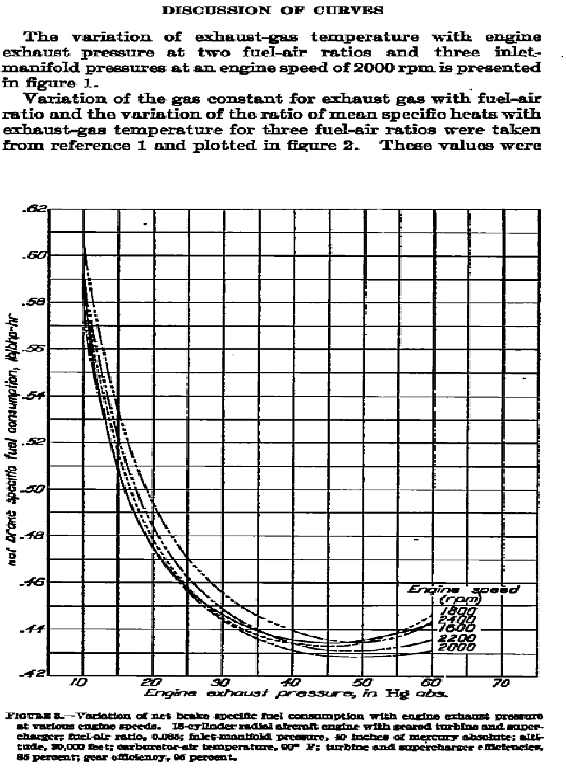
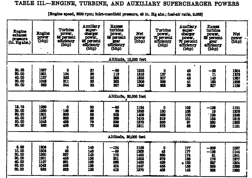
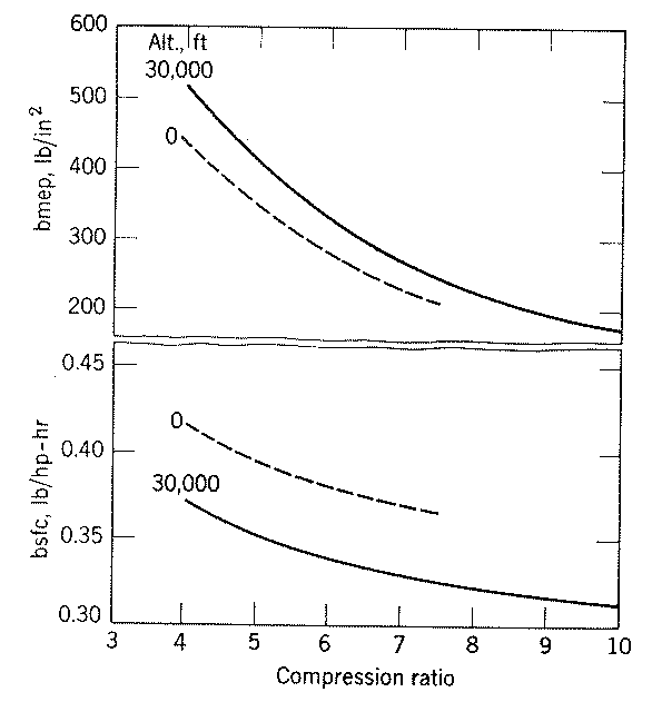
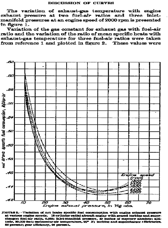
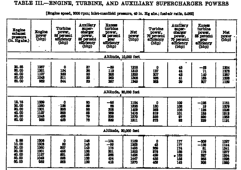
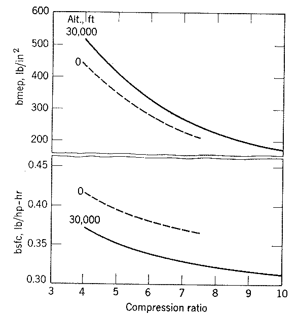
Here are a few charts for the R3350 TC and an early 18 cylinder radial TC.
You can download Report No. 822 technical paper from the NACA technical report server
web site.

Paul Lamar

The Rotary Engine NewsLetter.  Powered by Linux.
ACRE NL web site. http://home.earthlink.net/~rotaryeng/
Copyright 1998-2004 All world wide rights reserved.