Del Johnson wrote:
I woke up this morning at about 4 AM with the creative juices running. I
thought about how I might design a muffler that (1) pass the cooling air in
or around the muffler (rather than taking outside air as previously
discussed amoung this group) and at the same time (2) set up some form of
exhaust augmentation to pull the cooling air through the system.
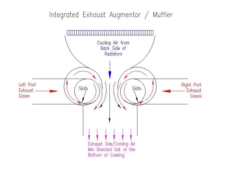
Before reading the next paragraph take a look a the drawings. My written
description may be difficult to follow without first seeing the drawing.
The concept muffler is depicted on the attached drawing. It shows a cross
section of the muffler. Each port would enter through a 1.5 or 1.75 inch
tube that would be midway across the muffler. That tube would be welded
perpendicular onto another tube of the same diameter that runs the length of
the muffler. The inner (smaller) tube that has slots cut into the bottom to
emit the exhaust gases into the chamber of a larger tube. The larger tube
would be offset from the center of the smaller tube and would be split with
one edge welded to the smaller tube just beyond the slotted holes. The
other edge of the split tube would be offset from the outer edge of the
small tube to allow exhaust gases to escape into a large cross sectional
exit area chamber that dumps the exhaust gases amd cooling air mixture out
the bottom of the cowling.
The left and right port exhaust chambers are symmetrical. They are placed
close enough together to transition the back side cooling air into a high
pressure zone and to promote exhaust augmentation (using the exhaust gases
to suck the cooling air out of the plenum). If the exit chamber is large
enough, so as not to create back pressure, the exhaust gases should not (
I;'m speculating) be inclined to move up into radiator plenum. Also the
swirling of the gases inside of the second, outer tube would help acelerate
and direct the gases out of the exit chamber. Depending on exhaust header
lengths there might be a drop in exhaust port pressures at the end of the
exhaust port cycle cause by the augmentation affect of the second port
beginning its exhaust cycle (again I'm speculating).
I should note that the exhaust chamber (bottom size of the drawing) should
be extended as far as possible to maximize the augmentation effect. A
considerable amount of cooling air is mixed with the exhaust so it should be
possible to use lighter, less heat tolerant material for ducting.
I haven't drawn any other views. The exit and entry plenums would start out
being part of the muffler (with extensions added using other materials).
Each end of the plenum/pipe assemby would be capped with a sheet of SS. I
would envision the muffler length to be 14 to 20 inches depending on the
space available under the cowling.
Approximately 1/4 of the outer tube containing exhaust gases is in contact
with the relatively cool radiator exhaust air. Also, approximately 1/4 of
the inner tube is in contact with the cooling air/exhaust air mix although
it is on the hotter side of the exit air mix. Both of these features will
help lower the temperatures in the material that makes up the muffler.
I don't know what affect that the slots and narrow passageways have on
reducing noice. Once the exhaust gases and cooling air mix it might be
possible to line the exit chamber with acoustical material to further reduce
the noise level.
OK, now it is your turn. Does this concept have any merit? Can we improve
upon it? Or the next time I wake up in the early morning hours should I
take a sleeping pill and go back to sleep?
It has some potential. You need to draw it to scale and see if it fits.

Paul Lamar


The Rotary Engine NewsLetter.  Powered by Linux.
ACRE NL web site. http://home.earthlink.net/~rotaryeng/
Copyright 1998-2004 All world wide rights reserved.
