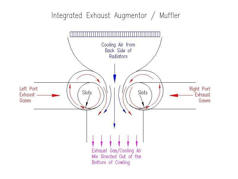
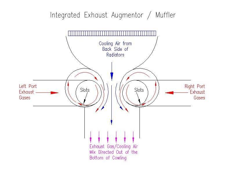
This is the VAM with a different exit. Not an idea. The only
question would be if
> there was any exhaust leakage prior to exiting the bottom of
the
cowl.
> Bill Jepson
Sorry! I seem to have mistyped. I meant to say, NOT A BAD IDEA! I
like
the concept if the backflow that was seen on the VAM isn't a problem. I
still like the VAM if you have room to extend a tube
forward to allow ram air to it.
Bill Jepson
Bill,
I thought that was unusually harsh for you Bill!

However I thought augmentors worked with the pressure
(exhaust )channelled
through the centre, thus pulling other less dense air from behind, using
a
bell shaped access - much like the inlet.

It would appear to me that the exhaust in this case is coming into the
sides. Does it work as well in this configuration - I guess the pressure
differences are still the same.
George (down under)
Del Johnson wrote:
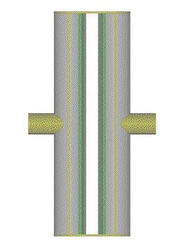
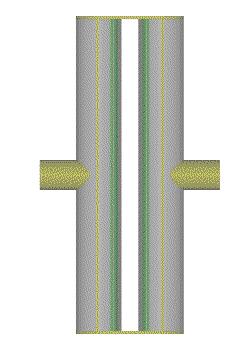
Attached is a 3-D rendering of the muffler as viewed from the bottom
(exhaust/cooling air exit side).  The exit chamber is the yellow rectangular
lines over the center of the tubes.  The green shaded area is inner tube
surface.  There is an 1/8" slit between the inner and outer tubes where the
exhaust gases escape into the exit chamber.  The white area in the center is
where the cooling air moves into the augmentor portion of the muffler.  The
intake plenum is not shown in the 3-D drawing.

I am concerned whether the exhaust gases can move up into the intake plenum
and into the cowling.  If the system acts as an exhaust augmentor, a vacuum
should form in the intake plenum.  If the exit plenum is designed to exit
the cowling parallel with the slip stream flow and is large enough so as not
to restrict the air flow, the gases should move down and out of the cowling.
It looks like this muffler would be easy to weld up.  A test muffler could
be welded with standard exhaust pipe and be used for static testing until it
burns out.  It would be very easy to build the muffler in two sections and
bolt them together with a plate so that you could test the effectiveness of
various gaps.

The NASA tests were done with the exhaust pipe centered at the entry point
of a larger augmentor tube.  I think what matters is creating a boundary
layer between the high speed exhaust gases and the slow moving cooling air.
If I recall, NASA had their best results with a flatten tube where there was
better contact with the incoming cooling air.  All of the Experimental
Aircraft exhaust augmentation implementations, that I know of, have been
very successful.  They use a standard round exhaust tube within a larger
augmentor tube (not elliptical).  The powersport powered Velocity, that was
at Oshkosh this year, is an example.  With the proposed muffler design there
is much more boundary area where the exhaust gases meet the cooling air.
This should enhance the augmentation effect.
The Rotary Engine NewsLetter.  Powered by Linux.
ACRE NL web site. http://home.earthlink.net/~rotaryeng/
Copyright 1998-2004 All world wide rights reserved.