| Subject: Cooling System Design Questions |
| From: ACRE |
| Date: 10/8/2004, 2:12 AM |
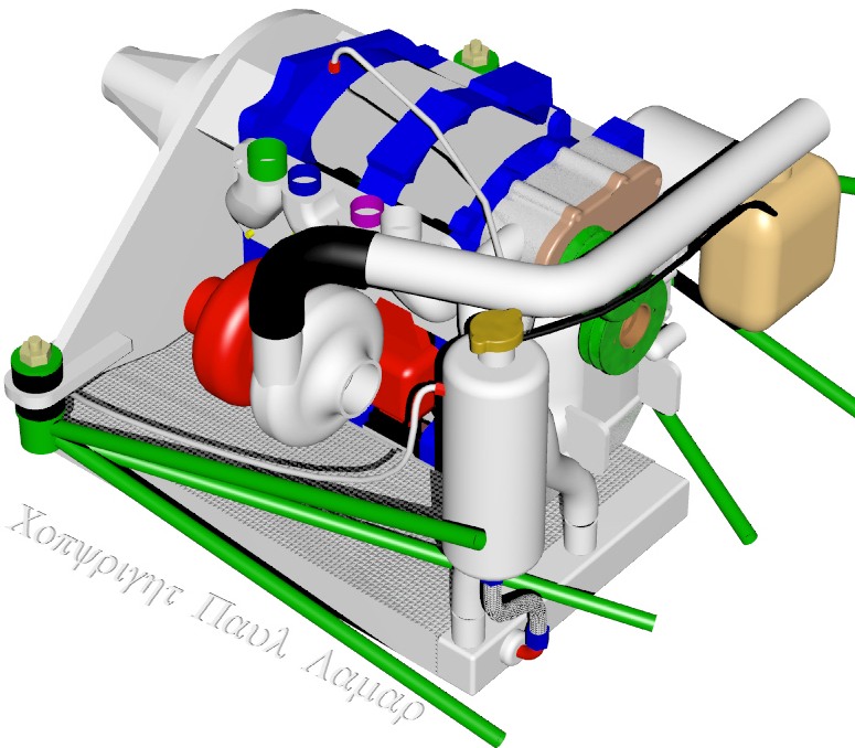
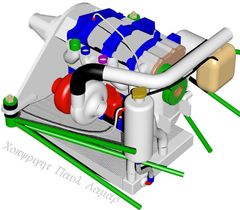
Del Johnson wrote:I have some questions about the cooling system and would like tofloatmydesign by the group before proceeding. Attached is a drawing that depicts the proposed system. The redlinesindicate the pressure side of the cooling system (outflow from thepump)andthe green lines reflect the low pressure side ( return flow). I would like to use the Mazda thermostat, to control there-circulationofcoolant in the water pump during cold operating conditions. Thehighpressure output line to the radiator will be through a welded on tapthat islocated below the thermostat so there should not be any restrictionintheflow to the radiator. The primary reason for using the thermostatisthat Iwould like to use an exhaust augmentation system which precludesusing acowl flap to regulating the exiting cooling air. I'm tight on vertical space in the cowling. Placing the radiatorcapimmediately above the thermostat might require a small bump in thecowling.I therefore included a separate small reservoir that has thepressurecap sothat it can be located elsewhere under the cowling. This unit alsocontainsone or more bleed line taps that will purge the system of steamvaporsshould the system overheat. I included in the design a lowpressurecheckvalve that will prevent the high pressure coolant from backflowingtothelow pressure side. Any buildup in steam pressure will open thevalve.What is the minimum size (volume) of the overflow bottle? How many lbs of pressure should the overflow bottle hold? If you are using standard car overflow bottles which make / modelcaroverflow bottle are you using? Any comments or suggestions on the design that I presented?That looks like it will work Del but you will be giving away some MPG and speed by using a thermostat instead of a cowl flap to control engine temperature. A cowl flap will reduce the cooling drag when max cooling is not required during cruise. The pressure in the system is about 25 psi when a 25 psi pressure cap is used. I recommend a 25 psi pressure cap as it increase the allimportantboiling temp. If the coolant boils that is a catastrophic enginefailureIMHO.Something around a gallon seems right for a pressure bottle. Here is the system I recommend. Note the pressure cap controls thepressureon the pump inlet side. There will be pressure drops throughout the rest of the cooling system. The Corvette has a nice metal pressure bottle. I had Ed Klepies weld one up for me so I could use highly reliable AN hose. More rotary powered airplanes have crashed by using low automotive qualityplumbingthan for any other reason. Paul LamarMy question concerning pressure was in regard to the overflow bottle. I assume anything less than 25 lbs (if your running 25 lbs on the othercap)would be ok. I was thinking about welding up my own metal bottle rather than usingtheplastic automotive ones but thought I would poll the group if plasticcaroverflow bottles were being used. I'm not sure that your point about loosing MPG and speed is correct ifI'musing exhaust augmentation to pull the cooling air through the cowling.Ifexhaust augmentation doesn't work out, I can remove the thermostat, plugtherecirculation hole in the pump and install cowl flaps.The over flow bottle is at atmospheric pressure so just about anythingwillwork that will take the heat. I think the correct NACA term for that is cooling air ejector rather thanaugmentor.The required length of an ejector makes them rather impractical for use with a single engine tractor. A twin or pusher is another matter. As I recall your ejector design is different and located under the rad. It looks like it will work but perhaps it would be too deep to fit into a stock cowl. Have you made any scale drawings yet? Also I think you should run both exhaust pipes into one side. I was thinking ofdoinga 3D for you on this but I did not think it would fit in a stock cowl. What kind of airplane are you building again? The thing about air ejectors is they primarily work at low speed when dynamic pressure is too low to force enough air through the rad. As the speed and air flow through the rad builds up they become less effective. That is when you need the cowl flap. Paul LamarPaul, Has anyone done a flow schematic with the inclusion of the pressure bottle? Am I correct in saying that the "pressure bottle" is actually a header tank? Do you intend am overflow tank as well, or a coolant recovery tank if you will? I am working on my radiator locations and tank placements. I haven't to this point had enough hands on time to get a good feel for routing. Do you, or has an ACRE subscriber done a flow layout? Anything you have will be helpful as I start getting into the plumbing layout. Thanks, Bill JepsonYes it is a header tank. You still need a coolant recovery tank. Not shown in the 3D. I guess I need to add that to the 3D. We discussed a real coolant recovery system a few years ago. I think we concluded you need a 50 psi pump to get the coolant back into the engine while the engine is still hot and running. Paul LamarFirst, to answer Paul's question: I am building a Glastar. There is quite a bit of room to work with both on the sides of the and underneath the engine. The cooling air ejector/muffler, that I proposed, places the two functions in parallel. The traditional serial connections (muffler followed by ejector) would be too long to fit under the cowling. I'm not sure that I agree with your statement (Paul's) that cooling ejectors work primarily at slow air speeds. Are there any studies that support your assertion that you will loose speed and MPG at high air speeds. I'm not an engineer but I design plumbing systems for large multistory buildings (apartment complexes, etc). An engine operating at, cruise (75% power) is like flushing a toilet or dumping a bucket of water into a mop sink. If the building isn't vented the water in the traps near the toilet (or sink) would be suck out. Regardless of air speed the cooling ejectors will create a vacuum and that vacuum should increase as the quantity of exhaust gases increase (which parallel engine cooling requirements). Only if the engine output is significantly reduced would the cooling ejectors affect become marginal. However, studies have shown that even at idle engine speeds there is still a cooling affect from the ejectors. There aren't that many airplanes flying with cooling ejectors but all the ones that I have heard about, report good cooling. Charles Airesman VariEze is an example of a fast airplane that incorporated cooling ejectors into the design. Responding to Bill Jepson's comments. I wasn't considering the coolant recovery bottle as a header tank. Why would you need a header tank? Cars don't use them anymore. All of the air should be purged from the system (except for the recovery bottle). Years ago, header tanks contained some air that buffered the expansion of the coolant. Didn't recovery bottles replace the expansion tank? Is there any advantage to maintain some pressure in the recovery tank (5 to 15 lbs)? On the question of the size of the recovery bottle: Does anyone know the volume of coolant taken up in the 13b engine? It would seem that if you know how much coolant it takes to fill the system that you could calculate the size needed for the recovery bottle if you calculate the expansion of the fluid over the operating temperature range. Del Johnson
I added an overflow can and some vent lines.

Paul Lamar


The Rotary Engine NewsLetter.  Powered by Linux.
ACRE NL web site. http://home.earthlink.net/~rotaryeng/
Copyright 1998-2004 All world wide rights reserved.