Jerry Hey wrote:
Paul, in the attached drawing, it is clear that if I stick with
straight line joinery with miters, exhaust sections running at
angles
will lose capacity.  I believe the solution is to use curves instead
of
corners.  Unfortunately, in my hands, drawing a curved line in cad
is
more difficult that cutting one out of stainless steel.   Could  you
model the pipe shape for me and send as an Iges file. Also at the
top,
near the muffler,  I will need to put in a slip connection, so the
need
there is  need for a short straight section.  The exhaust pipe in
question leaves the muffler at 45 degrees and continues for 10
inches
and then in turn down for 10 more inches. The section is 4 x 1.75
inches.   This is a real system that I will be building.  Thanks,
Jerry

Jerry Hey
j-winddesigns@thegrid.net
Is this a side view Jerry? If it were a front view the top part would
be
round.

Paul Lamar
Yes,  side view.  I want to have a curved version that follows the
same
path  roughly as the mitered version.  I want to keep the 4 x 1.75
section constant through out.  No round parts.      If this is a lot
of
trouble,  don't bother. I can lay it out in pencil..  I just don't
know
how to get the computer to do it.    Jerry
Something like this? The side view looks distorted but trust me... it
is
indeed constant area.

Paul Lamar
What a beautiful drawing.  This exhaust system is going in a BD-4.
The main difference will be that it exits the muffler on the center
line.  Thanks,  Jerry

Jerry Hey
j-winddesigns@thegrid.net
Well I need a sketch of where the rad is located to make sure it clears
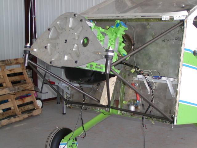
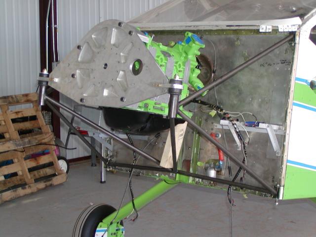
everything. Does it look the same as Bob Whites motor mount?

Paul Lamar

The Rotary Engine NewsLetter.  Powered by Linux.
ACRE NL web site. http://home.earthlink.net/~rotaryeng/
Copyright 1998-2004 All world wide rights reserved.