"Kent, Russell" wrote:
     >
     > Paul Lamar wrote:
     > > Way back in the early 30's when NACA was just getting started
     > > they commissioned the National Bureau of Standards to study
     > > radiator design for aircraft use. NACA Report No. 86
     > > Properties of Special Types of Radiators by S.R. Parsons.
     > > They coined a term they called "Head Resistance" and assumed
     > > there were no ducts or diffusers. In other words the radiator
     > > was stuck below or above the engine out in the air stream.
     > > Air flowing through the rad was the same as aircraft forward
     > > speed.

     > Shame on you, Paul, you know better.  There will be external diffusion
     > ahead of the radiator, causing slower, higher pressure air to flow
     > through the radiator.
     >
     > Russell Kent

     That is factored in by the way they ran the test in the wind tunnel.
     They noticed the effect by varying the spacing between the hollow
     plates from 1/4 inch to 1/2 inch. 1/2 inch gave better results. No doubt
     the study was flawed in several respects. It was also a strange mixture of theory
     and experiment. I am just saying the concept might have potential and should be
     revisited. What you are seeing here are probably Reynolds number effects.

     Also by installing such a heat exchanger in a modern diffuser the effect of
     air speed can be minimized. There is also not much chance of anybody coming
     up with the wherewithal to optimize this design unless NASA gets involved.
     However they seem too high and mighty.

     Paul Lamar

     My guess is that with the use of cowled rad with a diffuser, the same benefit of thicker rad can be had with the radiator fin construction now in common use.   The key to high efficiency
     is the high Delta T air temp through the rad.

     Sooner or later, you'll fly a thick rad : )

     Tracy Crook
I don't think so Tracy. Read Kays and London. This NACA work was done way before external
diffusion or the concept of a compact heat exchangers or the complete understanding of
what happens in a thick rad.

First of all the delta T in question is that between the rad metal and the cooling
air. You seem to be confused on that point. I think what you are referring to
is the increase in water temp as it flows through the block. I clarified this
on Bill's graph.

High increase in water temp actually hurts in a thick rad rather than helps. Assume
a 50 degree increase in cooling temp through the block. The water temp out of
the block is 200 F and the air temp is 100 F. The cooling water temp  drop through
the rad must equal 50 F or the engine will eventually over heat. Since one degree
increase in cooling air temp is a one percent loss in cooling effectiveness.
Assume for the moment that temp increase is also achieved by the air flowing
through the rad. That means half way through the thick rad the air temp is up
to 125 degrees F leaving a delta T of only 75 degrees. The last half of the
rad is now only 75% as effective as the first half. This is a crude approximation
of what happens. The rule of thumb is the first half does 3/4 of the cooling
and the last half does 1/4. The ideal heat exchanger is zero thickness with
infinite frontal area.

You don't need to take my word for it. Here is what Stewart Warner has to
say about it.

Paul Lamar
Here is what Kays and London has to say about it.
Let me translate  some of it [].

Paul Lamar
More pithy text from Kays and London.
Again I have added comments to make it relative to what we are trying to do [].

Paul Lamar

-------------------------------------------------------------------------
Introduction

The design of a heat exchanger involves a consideration of both the heat
transfer rates between the fluids and the mechanical pumping power expended
to overcome fluid friction and move the fluids through the heat exchanger.
For a heat exchanger operating with high-density fluids, the friction-power
expenditure is generally small relative to the heat transfer rate, with the
result that the friction-power expenditure is seldom of controlling
influence.

[What he is saying here is the HP consumed by the water pump is
of minor importance. In fact the Mazda pump only consumes about
3 HP.]

However, for low-density fluids, such as gases, it is very easy
to expend as much mechanical energy in overcoming friction power as is
transferred as heat.

[What is being said here is HP consumed by cooling drag. Since
cooling drag can be as high as 30% of over all drag the HP
could be as much as 30% of 200 HP or 60 HP. As you can see
cooling drag becomes a big issue.]

And it should be remembered that in most thermal power systems mechanical
energy is worth 4 to 10 times as much as its equivalent in heat.

[Here he is referring to the heat balance of most internal combustion
engines that only derive about 30% of the heat energy in a gallon
of fuel as mechanical energy out.]

It can be readily shown that for most flow passages that might be used for
the heat transfer surfaces of an exchanger, the heat transfer rate per unit
of surface area can be increased by increasing fluid-flow velocity, and this
rate varies as something less than the first power of the velocity. The
friction-power expenditure is also increased with flow velocity, but in this
case the power varies by as much as the cube of the velocity and never less
than the square. It is this behavior that allows the designer to match both
heat transfer rate and friction (pressure-drop) specifications, and it is
this behavior that dictates many of the characteristics of different classes
of heat exchangers.

If the friction-power expenditure in a particular application tends to be
high, the designer can reduce flow velocities by increasing the number of
flow passages in the heat exchanger.

[More tubes and more fins. In other words a larger radiator.]

This will also decrease the heat transfer rate per unit of surface area, but
according to the above relations the reduction in heat transfer rate will be
considerably less than the friction-power reduction.

[Pays off in cooling drag reduction.]

The loss of heat transfer rate is then made up by increasing the surface
area (lengthening the tubes), which in turn also increases the
friction-power expenditure, but only in the same proportion as the heat
transfer surface area is increased.

In gas-flow heat exchangers the friction-power limitations generally force
the designer to arrange for moderately low mass velocities.

[Done by the diffuser that converts velocity to pressure.]

Low mass velocities, together with the low thermal conductivities of gases
(low relative to most liquids), result in low heat transfer rates per unit
of surface area. Thus large amounts of surface area become a typical
characteristic of gas-flow heat exchangers.

[Lots of fins on the air side.]

Gas-to-gas heat exchangers may require up to 10 times the surface area of
condensers or evaporators or liquid-to-liquid heat exchangers in which the
total heat transfer rates and pumping-power requirements are comparable.

[Air to air intercooler.]

For example, a regenerator for a gas-turbine plant, if it is to be
effective, requires several times as much heat transfer surface as the
combined boiler and condenser in a steam power plant of comparable power
capacity.

These considerations have led to the development of many ways to construct
heat transfer surfaces for gas-flow applications in which the surface area
density is large. Such surfaces will be referred to here as compact heat
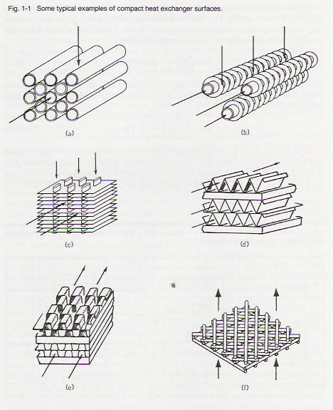
transfer surfaces.  Several typical compact heat transfer surface
arrangements are illustrated in Fig. 1-1.

Perhaps the simplest and most common surface arrangement for a two-fluid
heat exchanger is the circular tube bundle shown in Fig. 1-1a. This
arrangement, of course, has long been used for both high- and low-density
fluids, but the only way in which surface area density can be substantially
increased is to decrease the diameter of the tubes. Fabrication difficulties
and cost place a rather severe limitation on what can be accomplished in
this direction, and large heat exchangers with tube diameters of less than
tin. (0.006 m) are rare.

An effective way to increase surface area density is to make use of
secondary surfaces, or fins, on one or both fluid sides of the surface.
Figure 1-1 b illustrates a finned circular tube surface in which circular
fins have been attached to the outside of circular tubes. Such an
arrangement is frequently used in gas-to-liquid heat exchangers where
optimum design demands a maximum of surface area on" the gas side. Fins
could be used in a liquid-to-liquid heat exchanger, or on the liquid side of
a gas-to-liquid heat exchanger, but here another difficulty arises.  The low
friction-power requirement characteristic of high-density fluids, together
with the relatively high thermal conductivity of liquids, results in high
convection heat transfer rates in any optimum design (high heat transfer
coefficients). If fins are employed, the high heat transfer rates must be
conducted along the fins, and the conduction resistance may destroy all or
most of the advantage of the extra surface area gained (see the discussion
of fin effectiveness in Chap. 2),

Another popular variation of the finned-tube arrangement is shown in Fig.
1-1e. Here the tubes are illustrated as flat, but they can also be circular.
In compact gas-to-gas heat exchangers, large area density is desirable on
both fluid sides, and a method for accomplishing this objective with fins is
illustrated by the plate fin arrangement of Figs. 1-1d and e. The heat
exchanger is built up as a sandwich of flat plates bonded to interconnecting
fins.

[Popular configuration for intercoolers.]

The two fluids are carried between alternate pairs of plates and can be
arranged in either counterflow or crossflow, which provides an added degree
of flexibility in this arrangement.  Figure 1-1e also illustrates another
variation; the fins can be interrupted rather than continuous, an arrangement
which alters the basic convection heat transfer and flow-friction
characteristics in a manner that will be discussed presently.


The Rotary Engine NewsLetter.  Powered by Linux.
ACRE NL web site. http://home.earthlink.net/~rotaryeng/
Copyright 1998-2004 All world wide rights reserved.