"Kent, Russell" wrote:
     >
     > Paul Lamar wrote:
     > > Way back in the early 30's when NACA was just getting started
     > > they commissioned the National Bureau of Standards to study
     > > radiator design for aircraft use. NACA Report No. 86
     > > Properties of Special Types of Radiators by S.R. Parsons.
     > > They coined a term they called "Head Resistance" and assumed
     > > there were no ducts or diffusers. In other words the radiator
     > > was stuck below or above the engine out in the air stream.
     > > Air flowing through the rad was the same as aircraft forward
     > > speed.

     > Shame on you, Paul, you know better.  There will be external diffusion
     > ahead of the radiator, causing slower, higher pressure air to flow
     > through the radiator.
     >
     > Russell Kent

     That is factored in by the way they ran the test in the wind tunnel.
     They noticed the effect by varying the spacing between the hollow
     plates from 1/4 inch to 1/2 inch. 1/2 inch gave better results. No doubt
     the study was flawed in several respects. It was also a strange mixture of theory
     and experiment. I am just saying the concept might have potential and should be
     revisited. What you are seeing here are probably Reynolds number effects.

     Also by installing such a heat exchanger in a modern diffuser the effect of
     air speed can be minimized. There is also not much chance of anybody coming
     up with the wherewithal to optimize this design unless NASA gets involved.
     However they seem too high and mighty.

     Paul Lamar

     My guess is that with the use of cowled rad with a diffuser, the same benefit of thicker rad can be had with the radiator fin construction now in common use.   The key to high efficiency
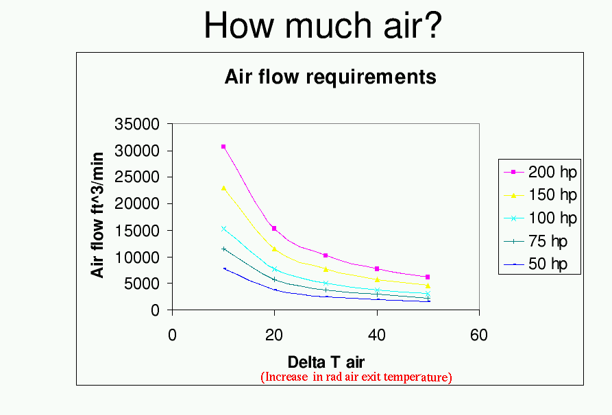
     is the high Delta T air temp through the rad.

     Sooner or later, you'll fly a thick rad : )

     Tracy Crook
I don't think so Tracy. Read Kays and London. This NACA work was done way before external
diffusion or the concept of a compact heat exchangers or the complete understanding of
what happens in a thick rad.

First of all the delta T in question is that between the rad metal and the cooling
air. You seem to be confused on that point. I think what you are referring to
is the increase in water temp as it flows through the block. I clarified this
on Bill's graph.

High increase in water temp actually hurts in a thick rad rather than helps. Assume
a 50 degree increase in cooling temp through the block. The water temp out of
the block is 200 F and the air temp is 100 F. The cooling water temp  drop through
the rad must equal 50 F or the engine will eventually over heat. Since one degree
increase in cooling air temp is a one percent loss in cooling effectiveness.
Assume for the moment that temp increase is also achieved by the air flowing
through the rad. That means half way through the thick rad the air temp is up
to 125 degrees F leaving a delta T of only 75 degrees. The last half of the
rad is now only 75% as effective as the first half. This is a crude approximation
of what happens. The rule of thumb is the first half does 3/4 of the cooling
and the last half does 1/4. The ideal heat exchanger is zero thickness with
infinite frontal area.

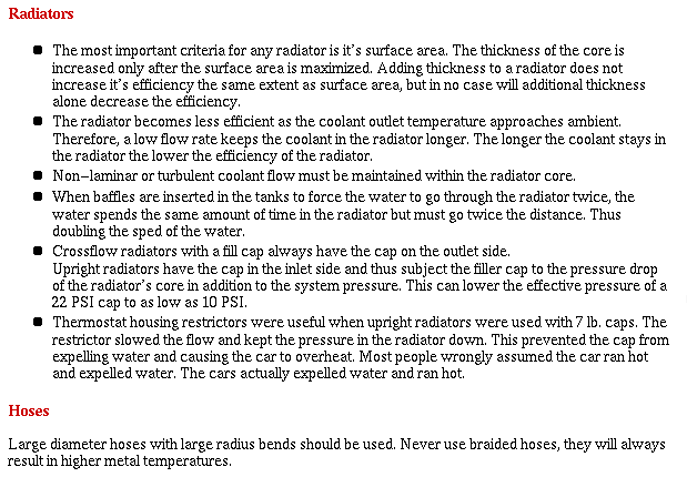
You don't need to take my word for it. Here is what Stewart Warner has to
say about it.

Paul Lamar

The Rotary Engine NewsLetter.  Powered by Linux.
ACRE NL web site. http://home.earthlink.net/~rotaryeng/
Copyright 1998-2004 All world wide rights reserved.