A kind person loaned me a Mezier electric water pump to run some
numbers on. I want to thank you for that.

First thing I noticed was the 20 AMP fuse in the 12 gage motor
wiring. Whoa! Wait a minute! That is a limit of 20 amps times 13
volts or 260 watts or .35 HP. As soon as you put some back pressure
on this pump either the impeller will cavitate or the fuse will
blow. The stock pump handles ten times that amount of HP or around
3.

Then I took it apart and saw the unsophisticated toy impeller and
decided testing it was a waste of time. A stock Mazda second gen
impeller looks like rocket science along side this toy. I expected
a much better design based on the questionable advertising claims.

The inlet and out let holes are limited AN -12 or 3/4 inch ID.
No way in hell are you going to get much flow through 3/4 inch
holes both on the inlet and the outlet. That is .44 square inches
and the usual water plumbing is 1.5 inch or 1.76 square inches or
four times more flow area. No way to increase the size of this
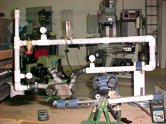
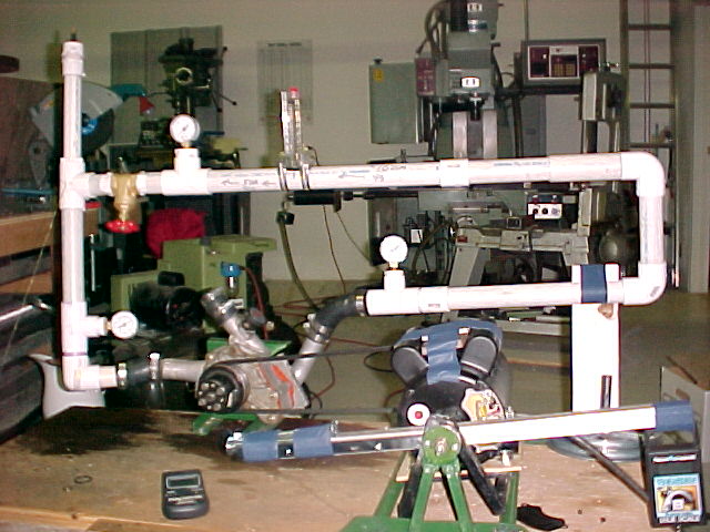
plumbing. In order to test this pump I would need to adapt the 3/4
inch plumbing to the 1-1/2 plumbing of my water pump test rig. Not
worth it!!!

Using this pump in a high powered aircraft engine risks cracking
the rotor housings due to local if not over all overheating.

Paul Lamar
There are still people out there that think these things work, I
think you should test it so we know what it's limits are.

Perry
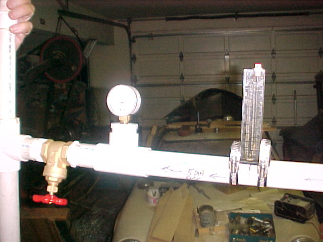
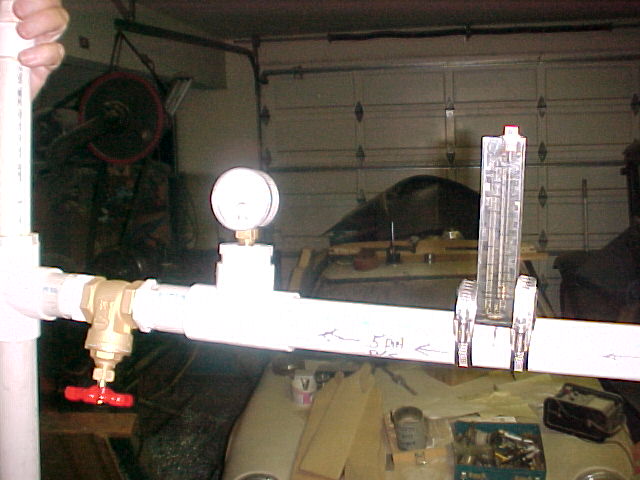
Any test I could do using my flow meter set up would be flawed due to
adapting the 3/4 pump plumbing to the 1.5 inch flow meter plumbing.
I think there would be a huge pressure drop on the inlet side and the
outlet side from inside the electric pump point of view. What the
pressure is inside the pump would be academic except for the fact it
affects the cavitation speed. I am unwilling to drill and tap the pump
body to measure this pressure change.

As far as I am concerned this is just a toy pump. It will not come
close to the stock pump performance when confronted by the overall
flow resistance of the cooling system at the flow rate required to
cool the engine at high power.

This pump also weighs 5 pounds. A bit less than the stock cast iron
second gen pump (6 lbs) but more than a 3rd gen and RX8 pump.

There is another factor that affects the required flow in the engine
and that is the serial nature of the Mazda cooling system. Water first
flows through the front rotor housing picking up heat in the process.
It then flows through the aft rotor housing and does not cool it as
well as it did the front. IMHO one reason way most people have trouble
with the aft rotor first as far as detonation and apex seal problems
are concerned.

The apex seal looses heat to and is cooled by the rotor housing. The
hotter the rotor housing the less it cools the apex seal. The apex
seal warps or goes into a banana shape as it heats up. It normally
runs about 500 F at its center. IMHO one reason the racers see a loss
in power at coolant temperatures over 180 F.

If you keep the flow rate up the two rotor housings will run at less
of a temperature difference and the better the heat transfer from
rotor housing metal to coolant.

To quote Kays & London:

"It can be readily shown that for most flow passages that might be
used for the heat transfer surfaces of an exchanger, the heat transfer
rate per unit of surface area can be increased by increasing
fluid-flow velocity, and this rate varies as something less than the
first power of the velocity."

Paul Lamar
Hi Paul,

The pump was sent at your invitation to test an EWP.  I thought the
purpose was to get data.  Why is the 20 amp fuse indicative of anything
other than the protective current for the motor windings. I've already
given you an approximate operating current reading of less than 8 amps
pumping from one open container to another.  Also the "toy" impeller is
giving about a 16 GPM flow under the same conditions.  In actual
operation, restricting the flow by blocking either the input or output
causes the current draw to drop to below 5 amps.  I also don't follow
your reasoning that adapting to your 1.5 inch system would somehow
invalidate any measurements.  Certainly the limiting element would be
the pump which is exactly what is being tested. Slowing the velocity by
using a larger pipe will give a more accurate pressure reading if
anything.

What would be of interest to me is the flow vs pressure and flow vs
current draw in a closed loop system as the system restriction varies.
However, if you don't care to do the test, I will find another way to
get the data.  The equipment I have available at the moment is
inadequate.

Thanks,
Bob White

--
http://www.bob-white.com
N93BD - Rotary Powered BD-4 (soon)
The 20 amp fuse is indicative of the max HP the electric motor
can generate. 20 amps times 13 volts is 260 watts. One HP is 746 watts.
Therefore  20 amps limits the max HP to .35. Since DC motors of this nature
are about 80% efficient the mechanical HP the pump is capable of
is .27 HP. It takes HP to pump water against back pressure.

The pump efficiency also enters into the equation. I don't have nay
efficiency numbers on centrifugal water pumps but I would
be very much surprised if it was as high as 70%. We are now down
to .19 HP. To be fair the Mazda pump also suffers from this but
I am willing to bet the Mazda pump efficiency is higher than this pump
judging by the looks of the impeller alone.

Yes of course blocking the flow completely will cause the impeller
to cavitate and the current drain to go down.

Since it is your pump and you are insisting I will compromise
with you. I will find a valve of about the right diameter,
put some back pressure on the pump and use the current plumbing
size to pump water out of one container to another in a give time
period.


Paul Lamar
Paul, I believe your flow meter is an orifice plate and measures the
differential pressure upstream and downstream to determine flow.  Is this
correct?

Regarding the flow measurement accuracy for the transition from 3/4" to
1.5" pipe.  I'm a control systems engineer and I spec a lot of these for
industrial applications.  The industry standard for these meters is to have
a minimum straight run of 10 diameters (ID) upstream and 5 diameters
downstream of the flow element (orifice plate).  This includes elbows,
valves, reducers, or fittings of any kind.  Hope this helps.

There is also a practical limit to the flow rates where you will get any
accuracy or repeatability.  If you have the specs for this meter (pipe ID
and orifice opening diameter) I can give you an idea of what the flow
measuring limits should be on that meter.  Or you may already have all this
info from the instruction manual.  We typically only give orifice plates a
3:1 or at most a 4:1 turndown ratio for accurate measurement (+/-5%).

Mike McGee, RV-4 N996RV, O320-E2G, Hillsboro, OR
13B in gestation mode, RD-1C, EC-2
No. It works off dynamic pressure. There is a pitto tube of sorts and
that diverts a bit of the flow up a tapered tube past a ball.

Paul Lamar

The Rotary Engine NewsLetter.  Powered by Linux.
ACRE NL web site. http://home.earthlink.net/~rotaryeng/
Copyright 1998-2004 All world wide rights reserved.