That was an interesting picture - since it was a submarine, the
purpose
may very well have been noise. A tip shroud rotating can be
handled
quite nicely with current marerials. On an early ducted fan at
GE
we used a segmented tip shroud of titanium as a part of the
labrynth
sealing of the stage. It did not use hoop, but was completely
carried
by a pin and clevis configuration at the tip of the 17-4ph
blades.
Carbon fiber in hoop can support a rather high centrifugal
load.
Vance
-> Larry Hendrix wrote:
Vance,
Both the picture and your comments are quite interesting, but I
could
not
follow all of your details. Do you have any pictures of that GE
fan
assembly, or references that I might find on the 'net?
Thanks,
Larry
george wright wrote:
Vance - are you referring to the GE lift fans that were tip driven
by
turbine exhaust?
To answer several questions - I set up an excell spread sheet to compute
hoop stress for several different diameters - but all with the same tip
speed - 900 ft/sec - near top value for most props (and compressor
blades
in most turbines by tne way). Funny thing - stress was the same for all
diameters at that tip spee - about 60ksi for carbon density (well
within allowable for filament wound uni). Stress goes up as the square
of tip speed, and is linear with material density. This is pure hoop
with no assist from the blades.
Advantages would be reduced tip loss and noise. reduced personell
risk (visibility and less chopping threat, damping for high aspect
ratio blading. There would be little impact on static thrust, but less
loss in top speed as compared to a stationary duct.

The attached sketch - from memory - shows the GE configuration,
and this was on a modest bypass ratio, early development engine,
and was not on any production fans to my knowledge. The tip
turbine lift fans were a favorite of Joe Alford - one of GE's
top idea gurus, and also did not make it into any production
systems to my knowledge. The seperation between turbine
and fan sections was accomplished by inegrated platform
"wings" - and this was also the case on the reverse case of
the aft fan "bluckets" - which did make it into production for
some Convair fanjets.

The contoured shroud configuration fan is ideal for blimp
applications, with improved low speed thrust, and a high
degree of protection for the ground crew. Many of these are
pivoted on drives similar to boat out drives, so they can
be pivoted for a wide range of thrust lines such as lift
and reverse.
- Vance
What about the increases skin friction of a rotating shroud.
Seems the HP consumption would be considerable because of the high
speed. A little bit additional drag at the tip results in large
increase in HP consumption due to the very high speeds.
Marc De Piolenc already mentioned this.

Paul Lamar
I do not think that it would be as much as you think. The shroud
1 would think about would be only 3 or so inches wide, and
skin coeff are pretty low - about like the losses in an energy storing
flywheel - orders of magnitude less than a typical countoured
fixed shroud with it's attendant struts - probably a few percent
but maybe a net loss when subtracted from reduction in tip
losses. I just said it was quite possible - no claims of
great breakthroughs - Vance
A fixed shroud on an air boat is going 50 mph. A rotating
shroud the same width is going 12 times as fast or 600 MPH.
The dynamic pressure at 600 MPH is 144 times greater.

The dynamic pressure at 50 MPH is 6.5 pounds per square
foot. If the shroud is 3 inchs wide and 36 inches in diameter the the surfaces area
is 4.7 square feet. Both sides.  If the skin friction drag coefficient is .002 (Von Doenoff)
drag at 50 MPH would be .06 pounds. Near zero HP for such a small shroud.

At 600 MPH and a dynamic pressure of 936 pounds per square foot drag would be
8.7 pounds. 600 MPH is 880 feet per second so 8.7 pounds times 880 feet per
second is 7,656 pound feet per second or 14 HP.

This is a tiny shroud by shrouded or ducted prop standards. I assume you are going
to incorporate this into a larger duct. Is the reduction in tip losses really worth
a 14 HP penalty?  I doubt it and that is probably the reason they are never used.

I agree with Marc de PioLenc on this.

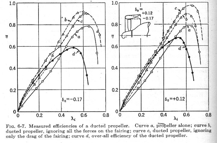
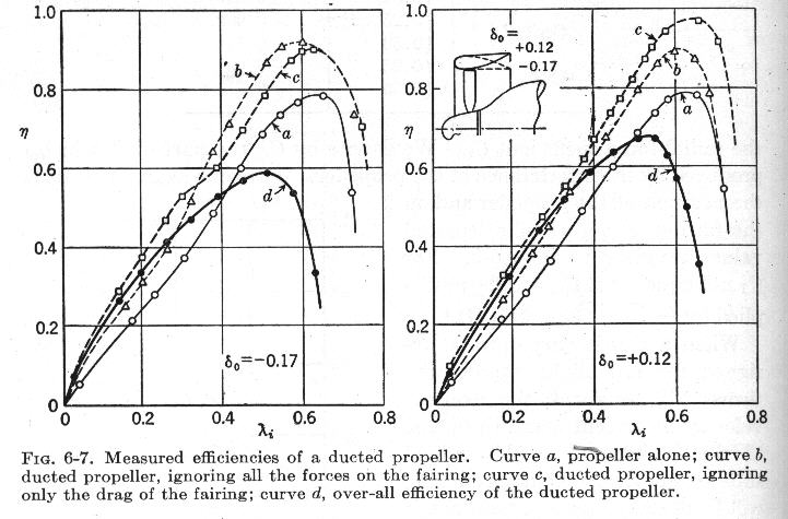
We already know that the drag of a ducted fan in the speed ranges we fly
is much greater than the unducted propellor. Perry Mick has proved that with
his extensive experimentation. K and M says the same thing. I don't think adding
a rotating tip shroud consuming and additional 14 HP is going to help.

Paul Lamar

The Rotary Engine NewsLetter.  Powered by Linux.
ACRE NL web site. http://home.earthlink.net/~rotaryeng/
Copyright 1998-2004 All world wide rights reserved.