Jarrett Johnson wrote:
Sorry Paul, I guess I should read all my emails before replying..
thanks for
the info I'll get to work. It might not get completed until later
today
or
early tomorrow am as I'm away for most of today.

Jarrett
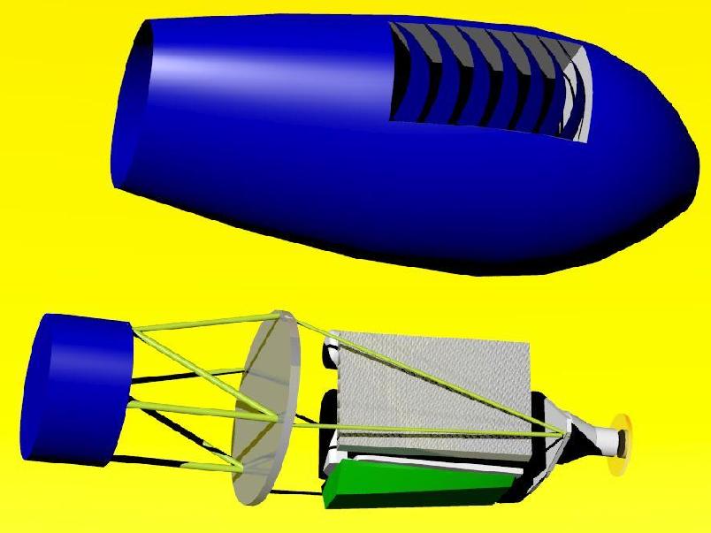
I borrowed your technique of the union of two separately lofted
solids.
Works well for cowlings  and is easy and quick to do. Here is a quick
and
dirty
example done in Rhino. Rhino does not do filets between compound
curved
solids very well. IMHO Solid Works does a much better job at that.
Filets could also be done by hand at the male buck construction
stage.

This looks easy to do and can be expanded to four or more solids
in the case of cheek inlets. Good idea on your part. Thanks


Paul Lamar
No Problem Paul, Let me say off the top, I'm sure there are a bunch of
guys
on this list that are
better at doing these types of things than me [ I've been at it for 1.5
yrs
only] an its pretty simple
to do. Anyway.. I put your engine mount into the cowl, changed to a
rectangular  inlet with full
round ends [ok it's not perfectly rectangular- there is a slight curve
to it
still as I can't stand
to see boxy straight stuff in something built from composites  :-)  ].
However I found that the
mount was sticking out of the cowl [ 30.2" wide at the front] so I
decreased
that to ~25" but its
still sticking out. I don't have any dim's on a PSRU so I didn't put
that
in. Also if you had some
ruff dim's for a rad I could put that in as well, along with a duct for
it.
I'm thinking that we should have
some sort of cowl outlet and we might as well put that in at this
point. Do
you have any dim's for inlet
and outlet area's. I know it should be at a ratio of 1:1.5 or so, but
haven't taken the time to do
much in the way of calculating for cooling.

Does Rhino have a shell function? I used to do alot of single body
lofts and
then one day
had the idea to do multiple lofts with the 'merge solids' function and
then
'shell' the parts
afterwards. It's worked reasonably well for me on most things, however
there
are points
where a surface loft that is later thickened is a better way to go. 3-D
work
started out as
a frustrating thing at first but with time.. and many tries, you learn
what
will and won't work
and go from there. Again, I'm by no means an expert.

Hope this helps others that are working with these programs.

Jarrett

BTW, where do I find text wrap in Outlook Express, I've been just
shortening
my
used space across my screen but what a pain in the butt.  Help in that
regard would be
great!
Good work on the cowl. Maybe we need to go to a larger spinner and move
the scoop down a bit. I'll give that a try.

You got me on the text wrap. I use an old version of Netscape on Linux.
I have newer version but this old version is very fast.

Paul Lamar
26 inches center to center on the motor mount and a 16 inch spinner.
The bigger spinner is the key. Looks better too.

Paul Lamar
I can't seem to get 26" to work. I think the reason is I'm trying to get my
cowl as stream-lined as poss.
I've got it at 18" c-c right now.. and that fits but its alot tighter than
what you've got to work.
I threw a dummy rad and plenum into it as well just for looks, along with a
16" spinner and prop.
Any other suggestions that could /would improve?  This has been fun working
w/ you over this.
At least my coffee breaks have been interesting.  :-)

Also, you'll notice that my mount is tight at the lower firewall loc's,I
moved them in about an inch
to make it work as well.

BTW if you'd like I'd be glad to pass on a IGES file of what I have.

Jarrett
The cooling system works better if the air comes in over the top of
the rad and goes out an open bottom with venetian blind type cowl
flaps. The wedge shaped duct above the rad then shields it from radiation
from the red hot exhaust. Also anything behind the rad such as an oil pan
builds counter dynamic pressure reducing the flow through the rad.
A rule of thumb is 10 inches of clear space behind the rad. More for
really big rads.

26 center to center is about as short as you can make the MM beam and still
get a six inch muffler can or turbo charger in there.

The pdf file was too large to publish. Got that is some other format?

Paul Lamar
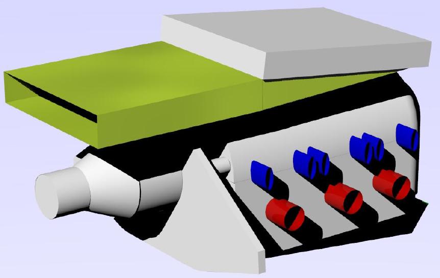
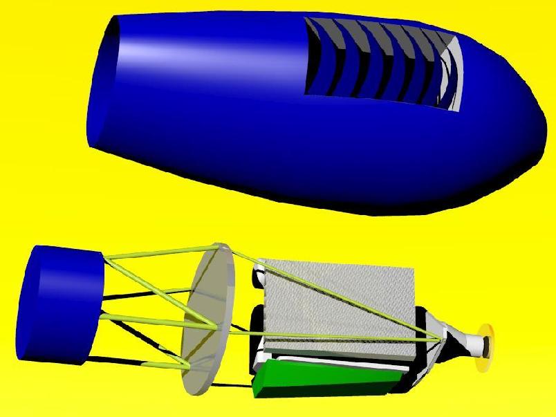
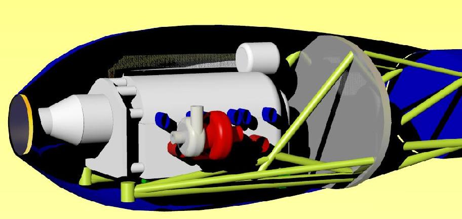
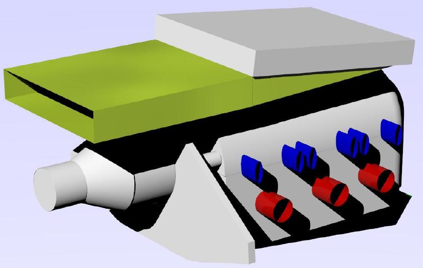
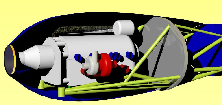
Jarret I see the clearance problem in your side view. The bottom of the MM
cross beam
is too low. The bottom of the beam is flush with the bottom of the block. That
moves
the rubber motor mounts up giving more cowl clearance.

Here are a few views of mine. This has the rad in the bottom, the muffler
and a 26 inch center to center rubber mounts. the exact fore and aft
position of the rad is going to depend on the nose gear.

What ever. The RV10 has room for two three rotor engines :)

Paul Lamar
Paul
The RV-10 cowl with the rotary residing within reminds me of the early 55
Chevys with all of that space on each side of the engine.

With a similar aircraft engine bed mount on my Seawind, and the enormous
amount of room behind the engine, I could almost mount the radiator at an
angle back there and blow the heat out through cowl flaps on the top.

Doug in Japan
I did a few Sea Wind layouts with the stock cowl more or less.
Here are several.

Paul Lamar

The Rotary Engine NewsLetter.  Powered by Linux.
ACRE NL web site. http://home.earthlink.net/~rotaryeng/
Copyright 1998-2004 All world wide rights reserved.